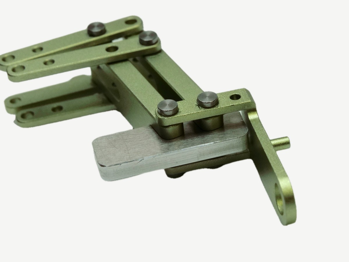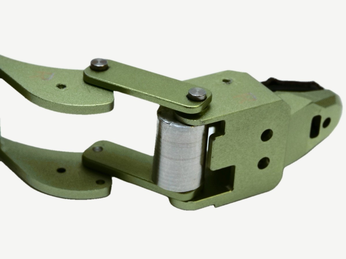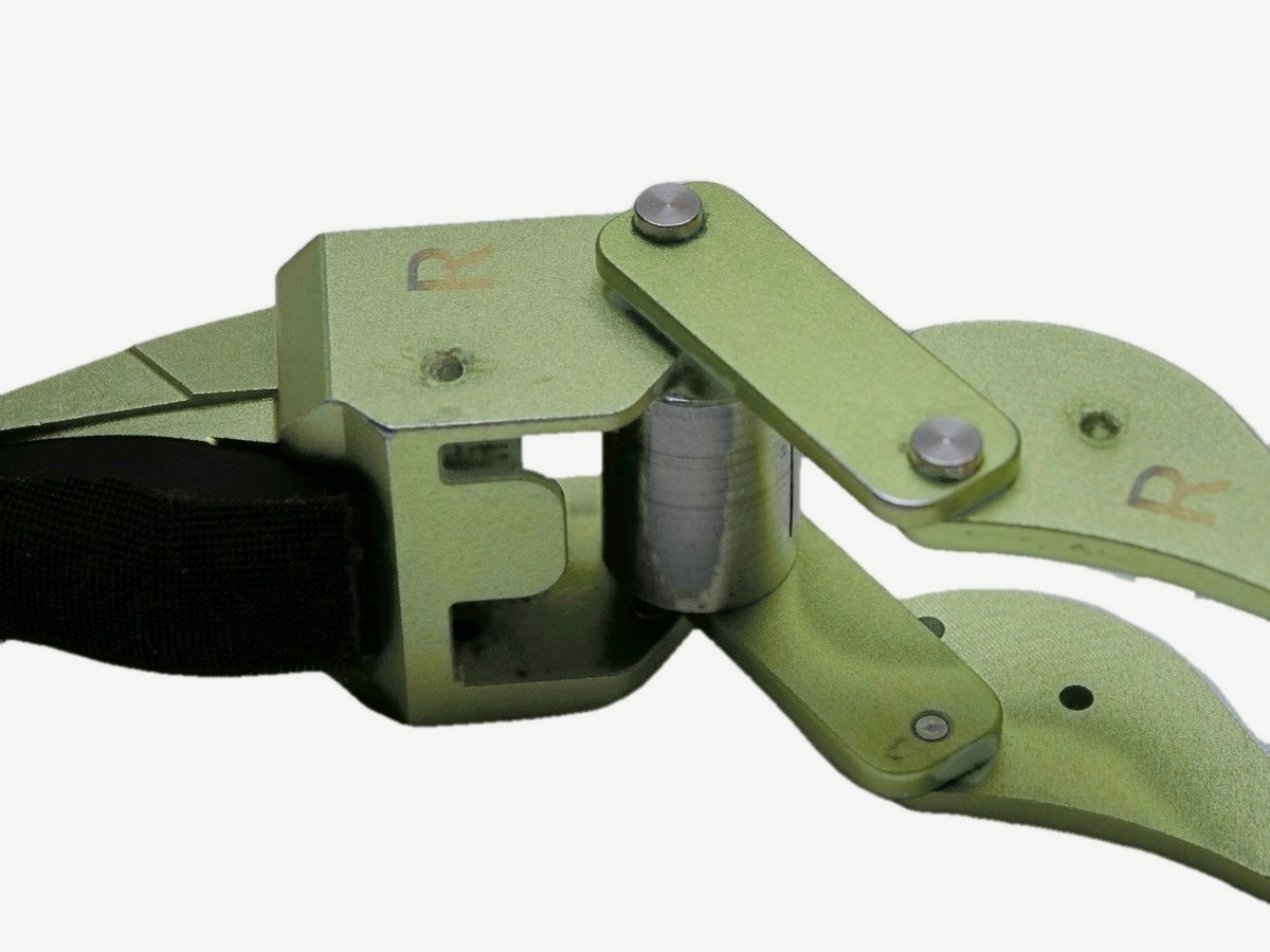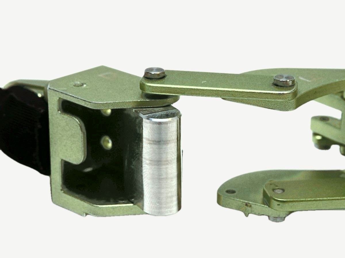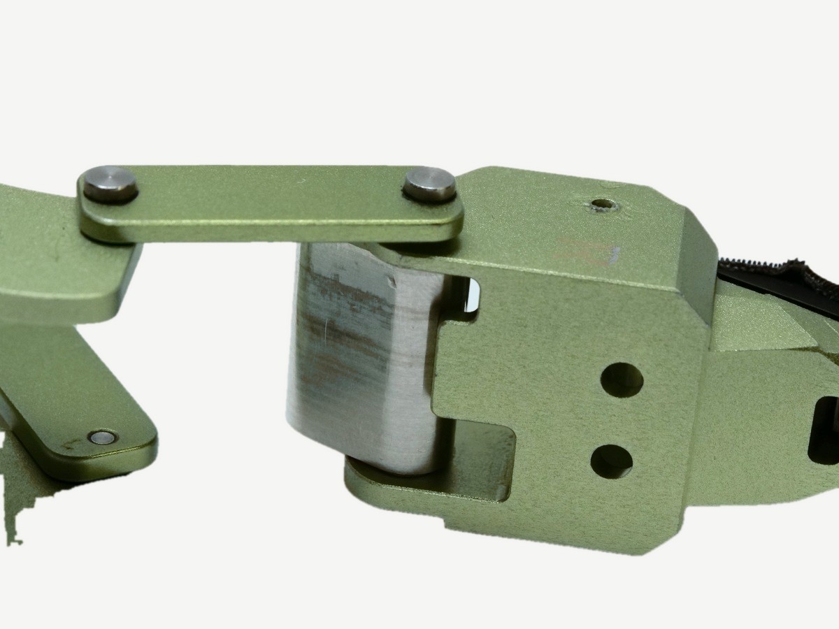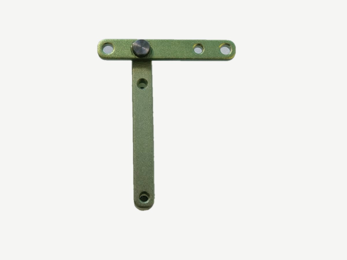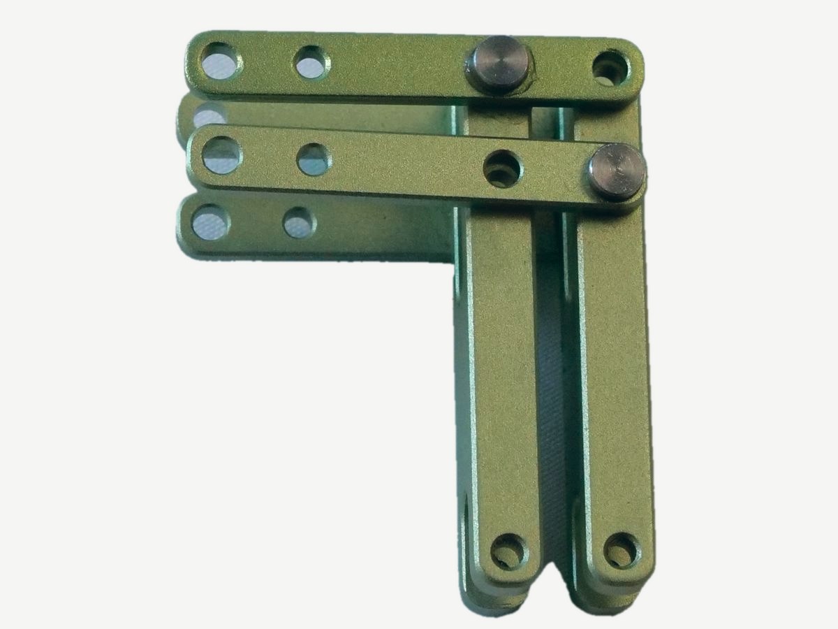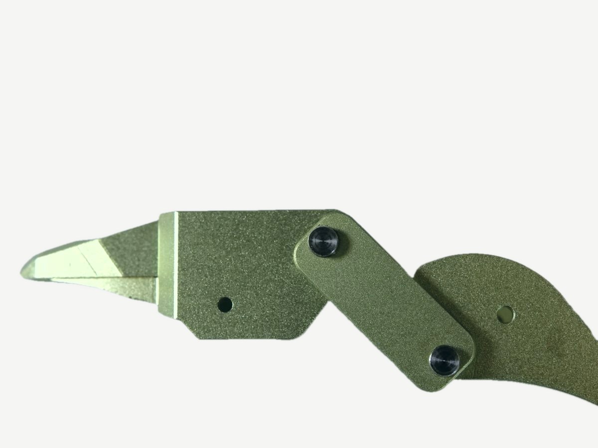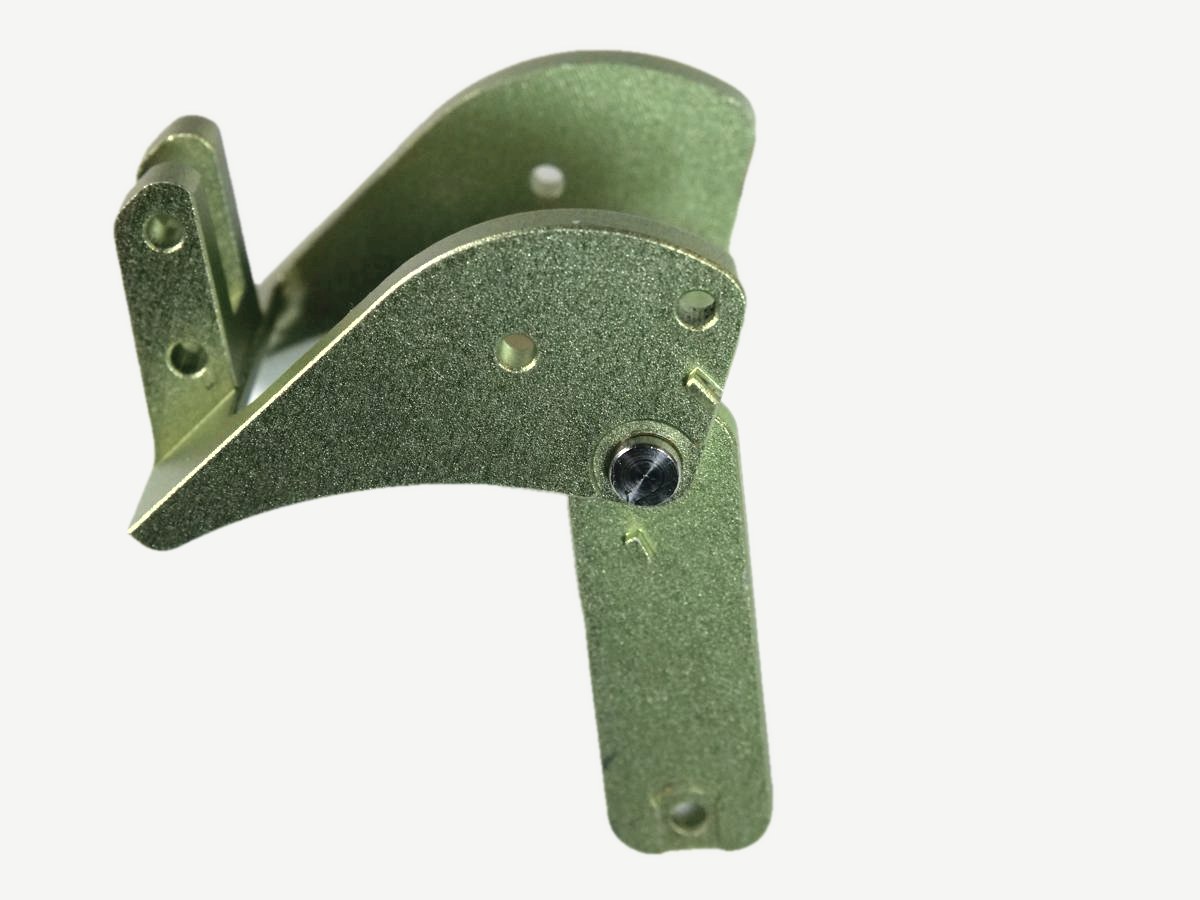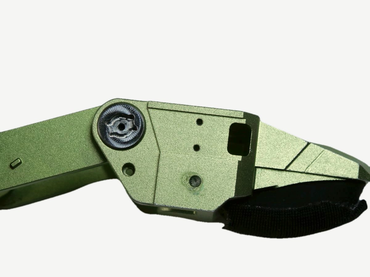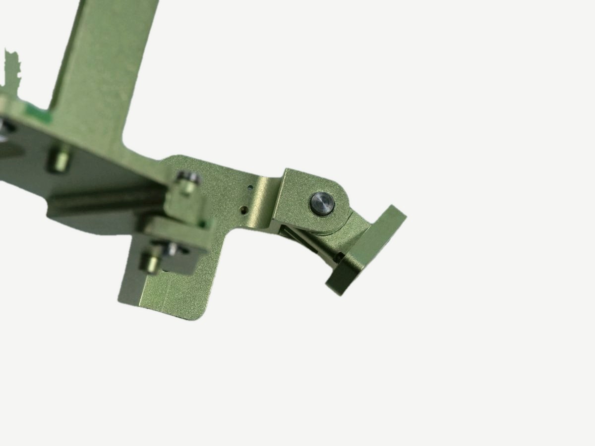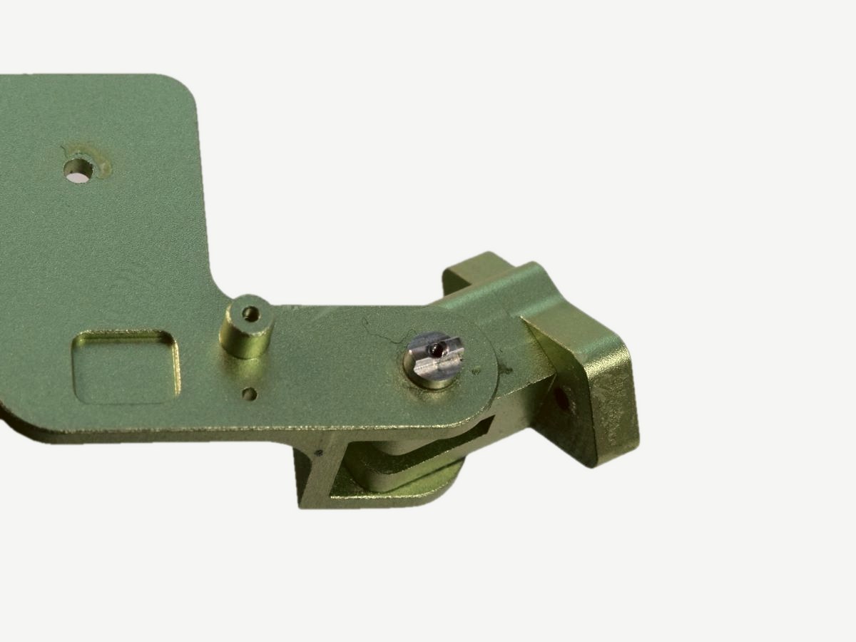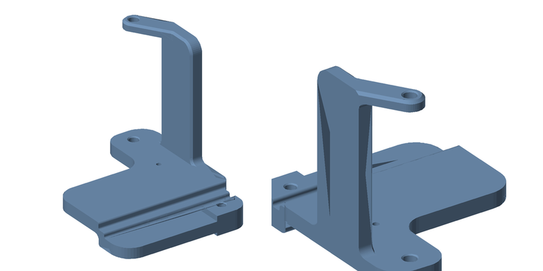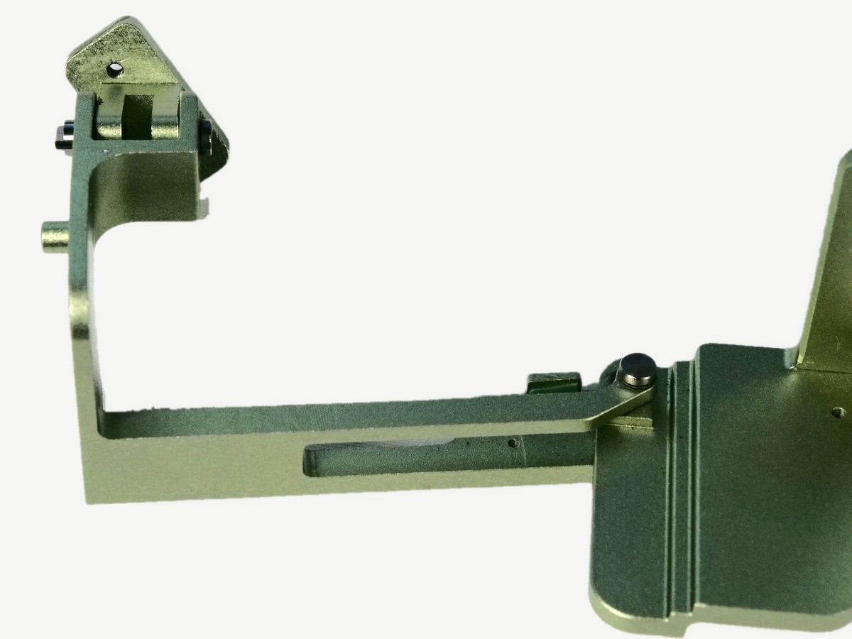

GEAR DexUMIDocumentation
GEAR DexUMI / Hardware Guide

Hardware Guide

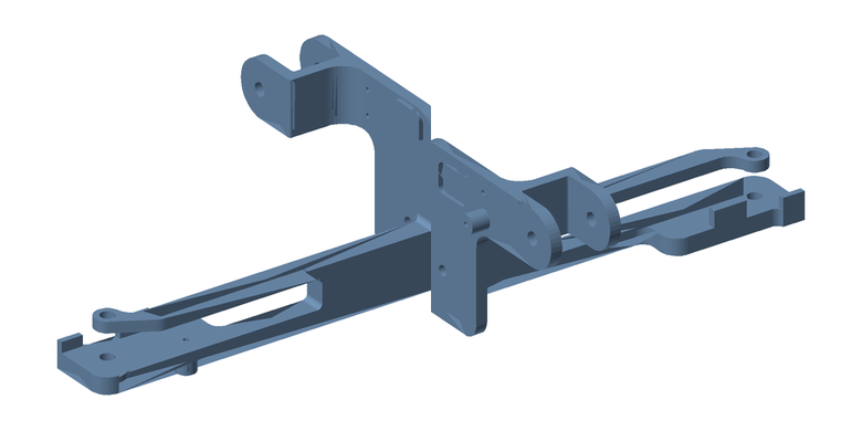
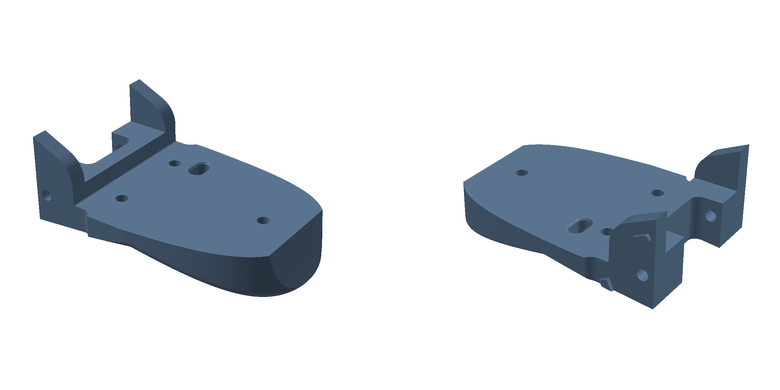
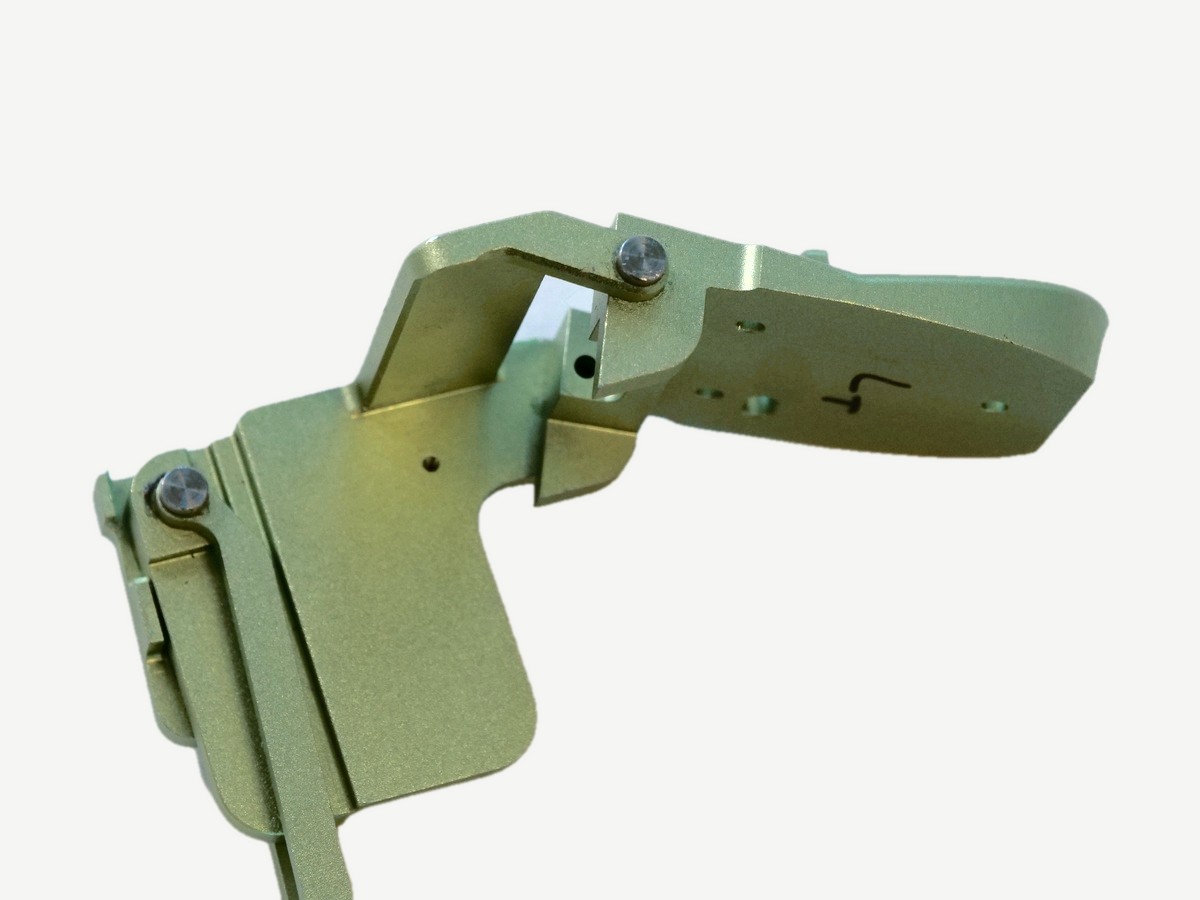
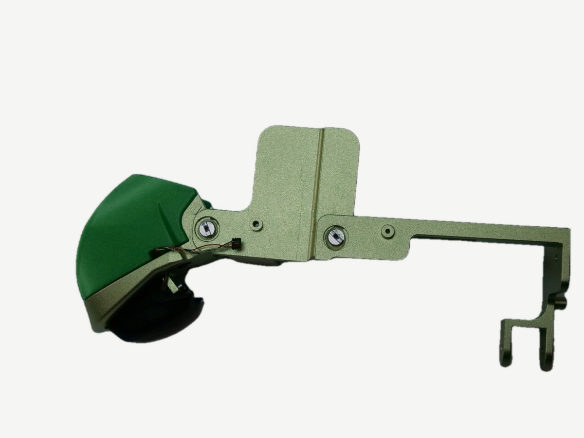
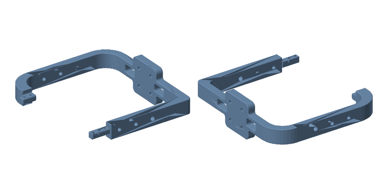
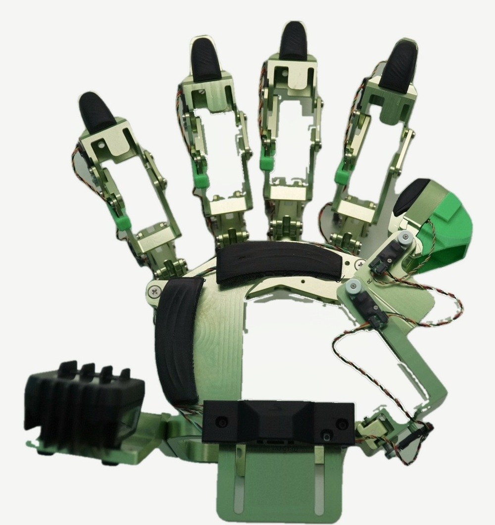
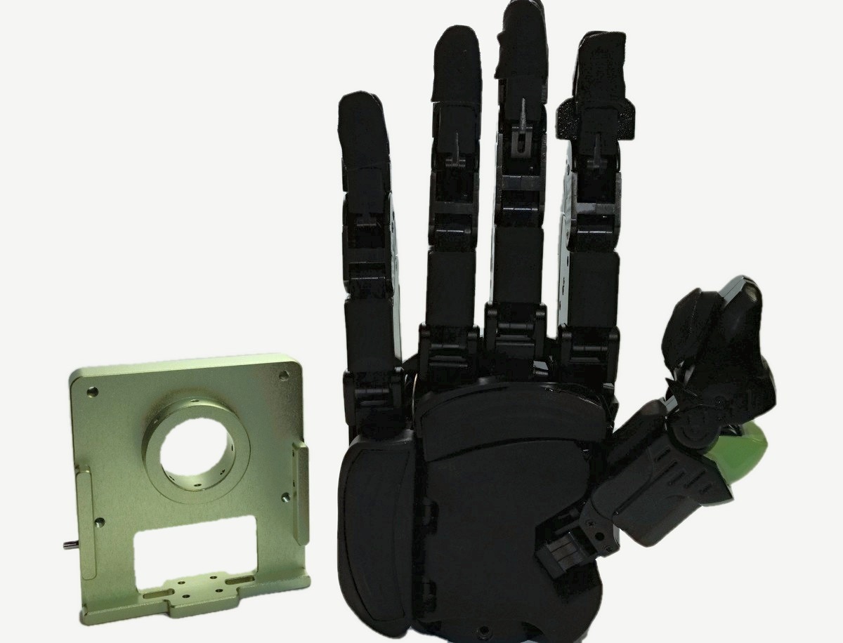
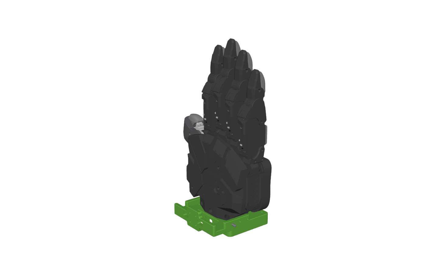
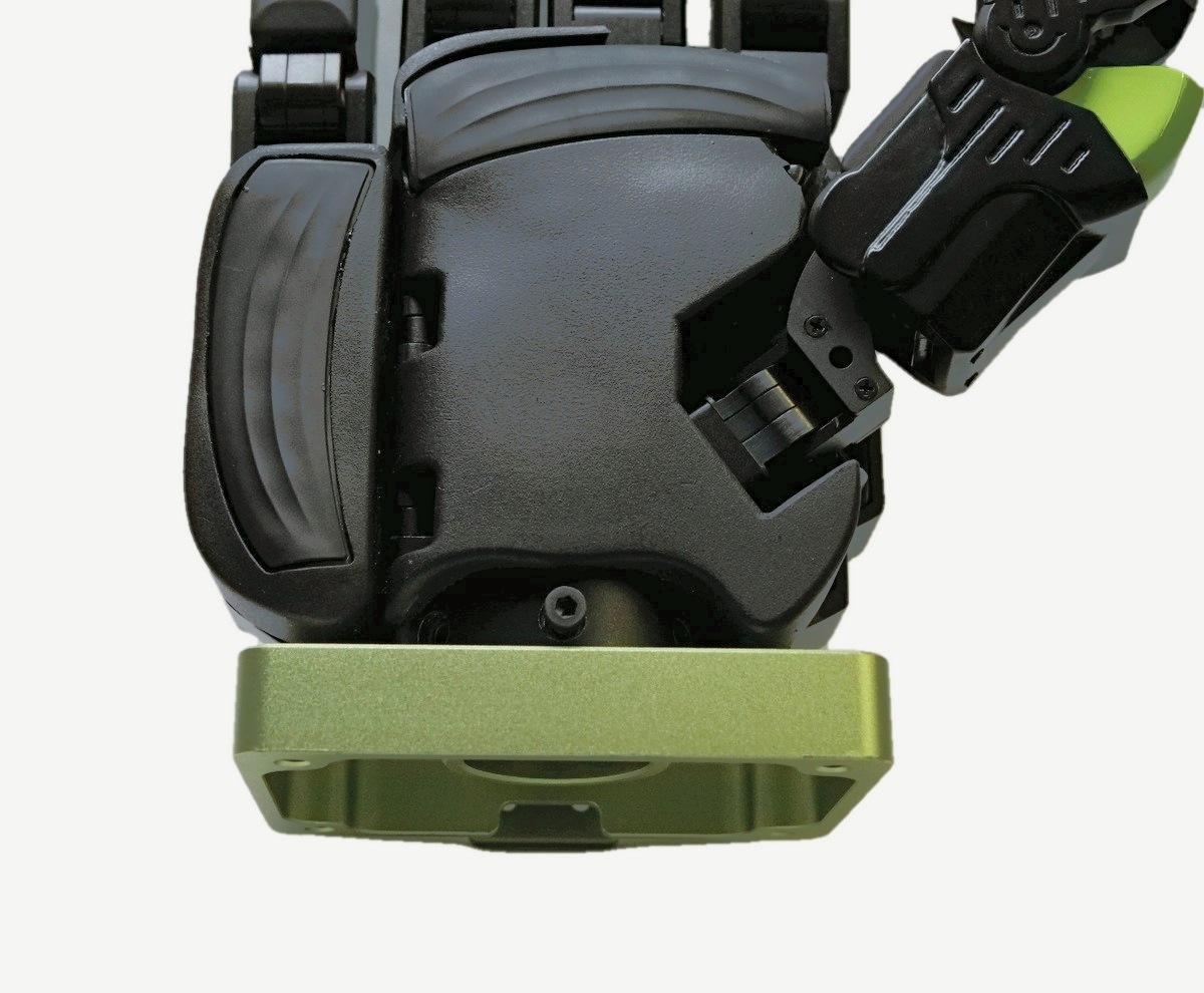
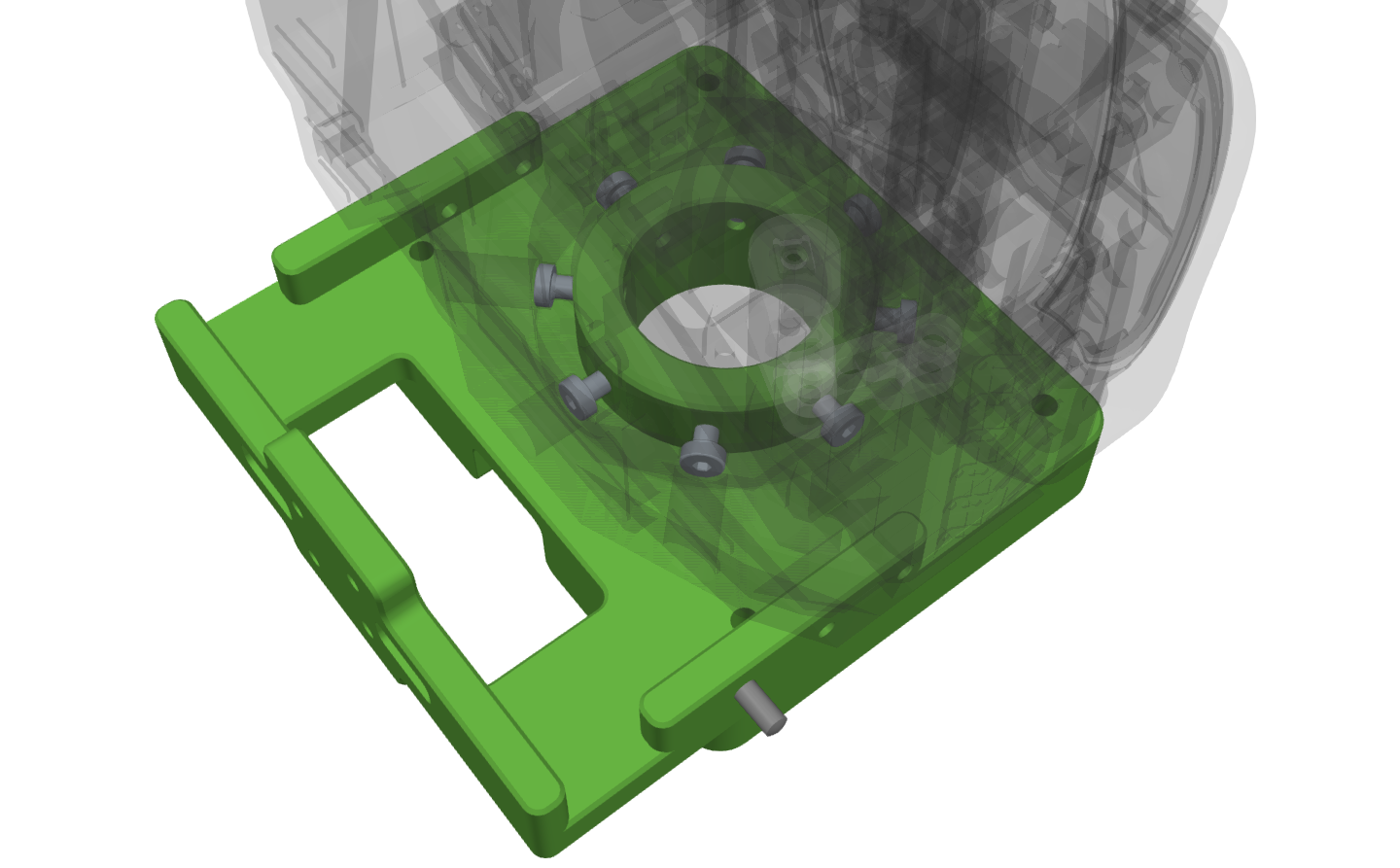
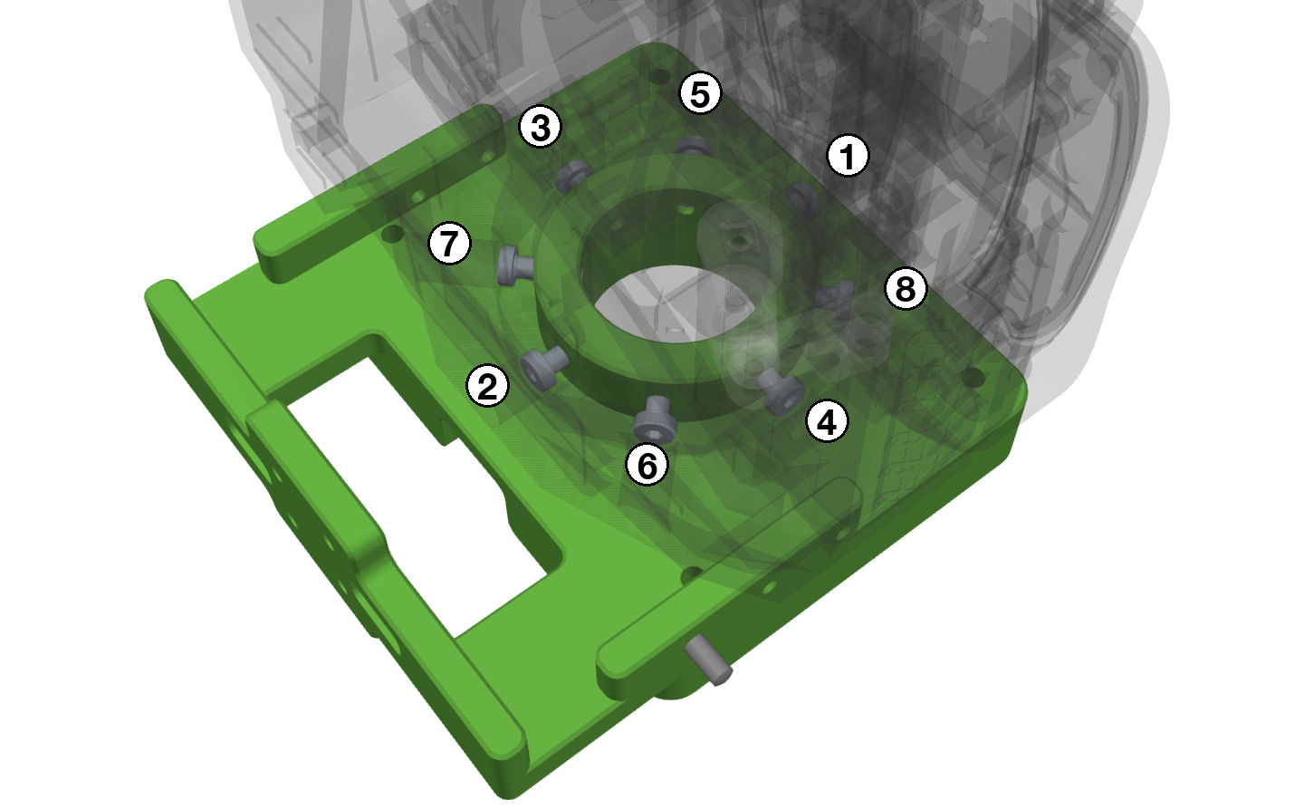
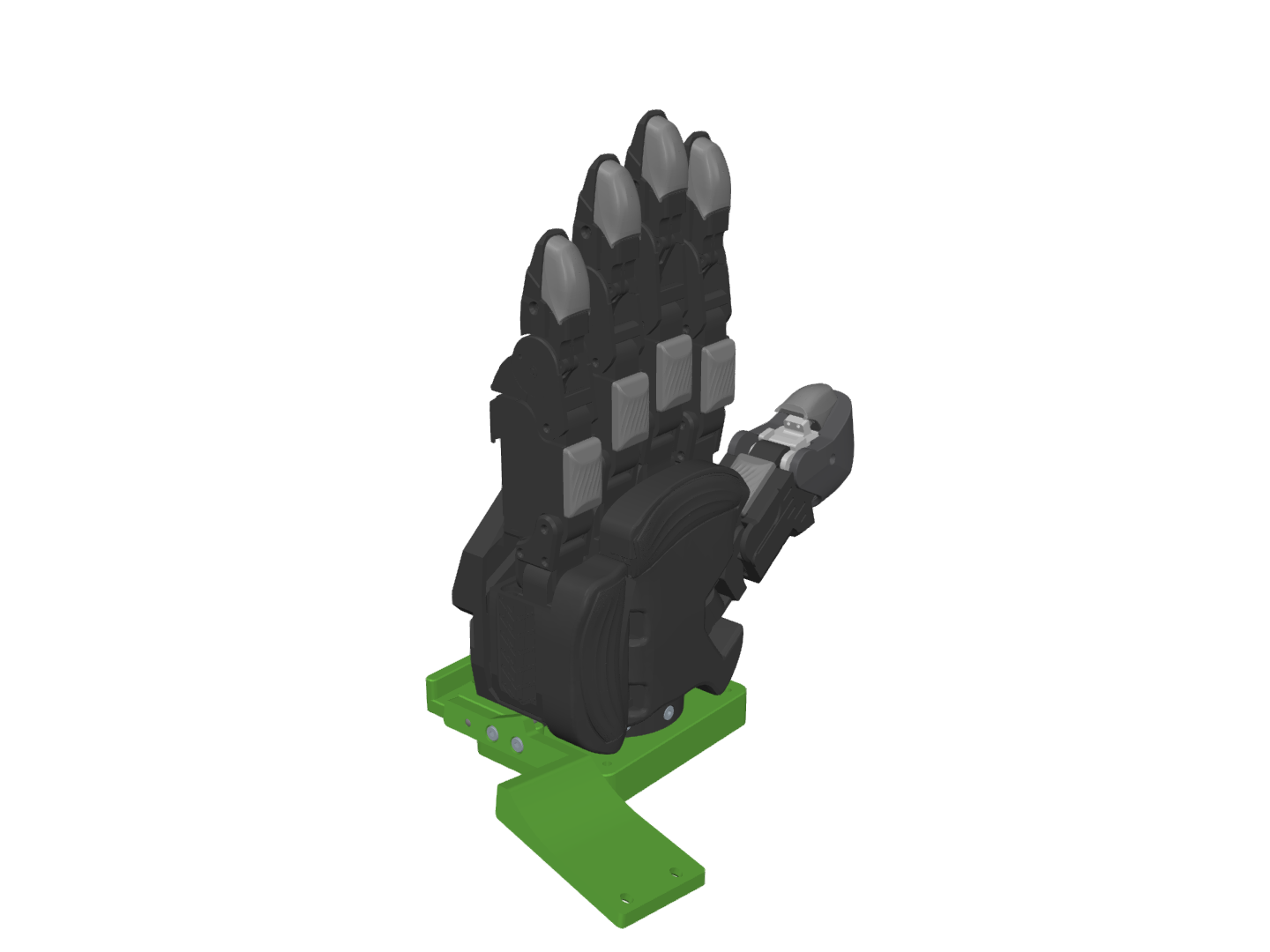
3D model

Click a part to jump to the steps that build it. Drag to rotate, scroll to zoom.

Tools and software

The full tool list, with vendors and links, is in the Bill of Materials.

Tools

  • Manual arbor press (0.5–1 ton)
  • Precision driver kit
  • Loctite dispenser kit with nitrile gloves
  • Pin and shim alignment tweezers
  • Anvil block set (123 block and V block)
  • Metric Allen key set

Software

Press-fit tools

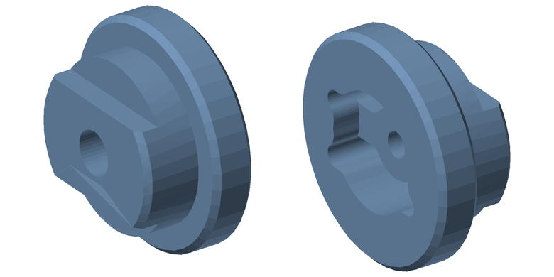
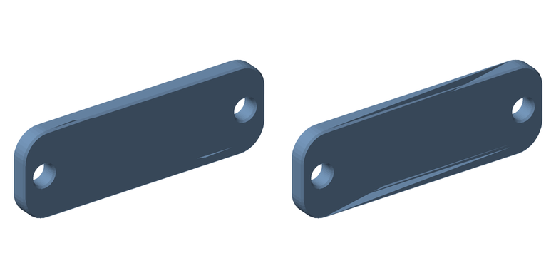
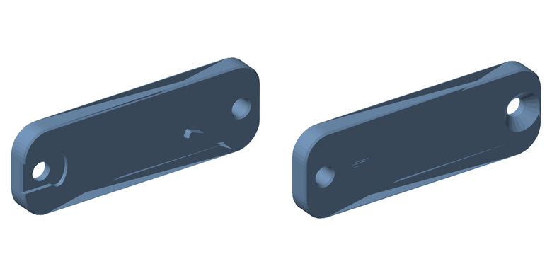
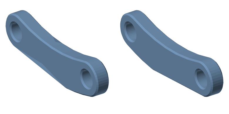
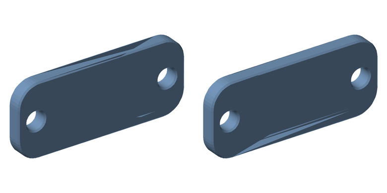
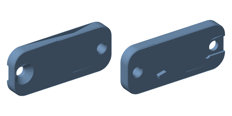
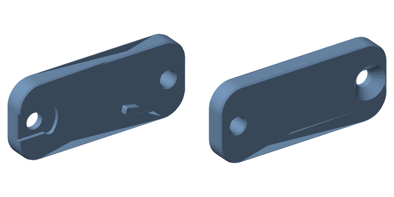
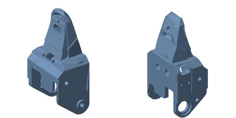
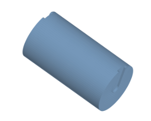
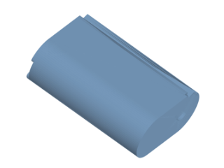
These 3D-printed tools hold parts apart or in place while you press-fit.

ToolSize (mm)Used in
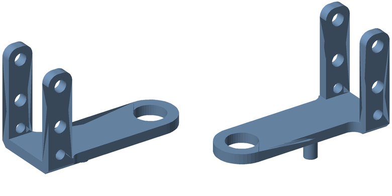
DU-TOOL-01DU-TOOL-0112.0 × 12.0 × 17.4Steps 8–10
DU-TOOL-02DU-TOOL-028.8 × 15.4 × 20.0Steps 8–10
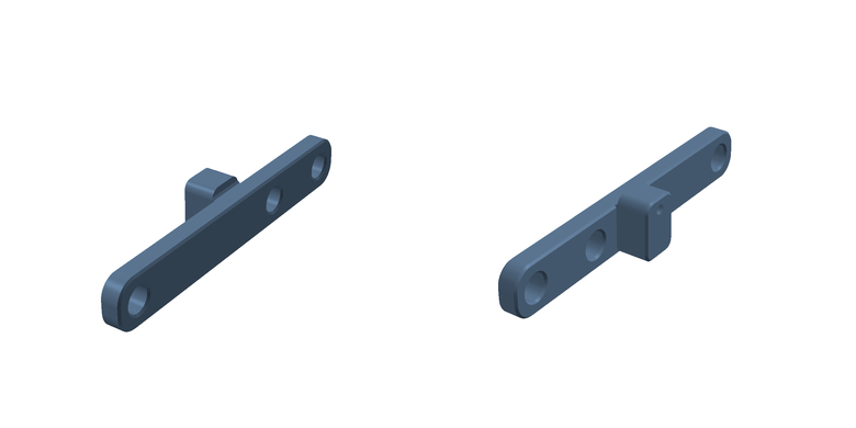
DU-TOOL-03DU-TOOL-0330.0 × 10.0 × 3.9Steps 1–7

Print instructions

1

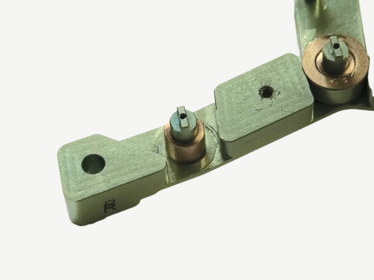
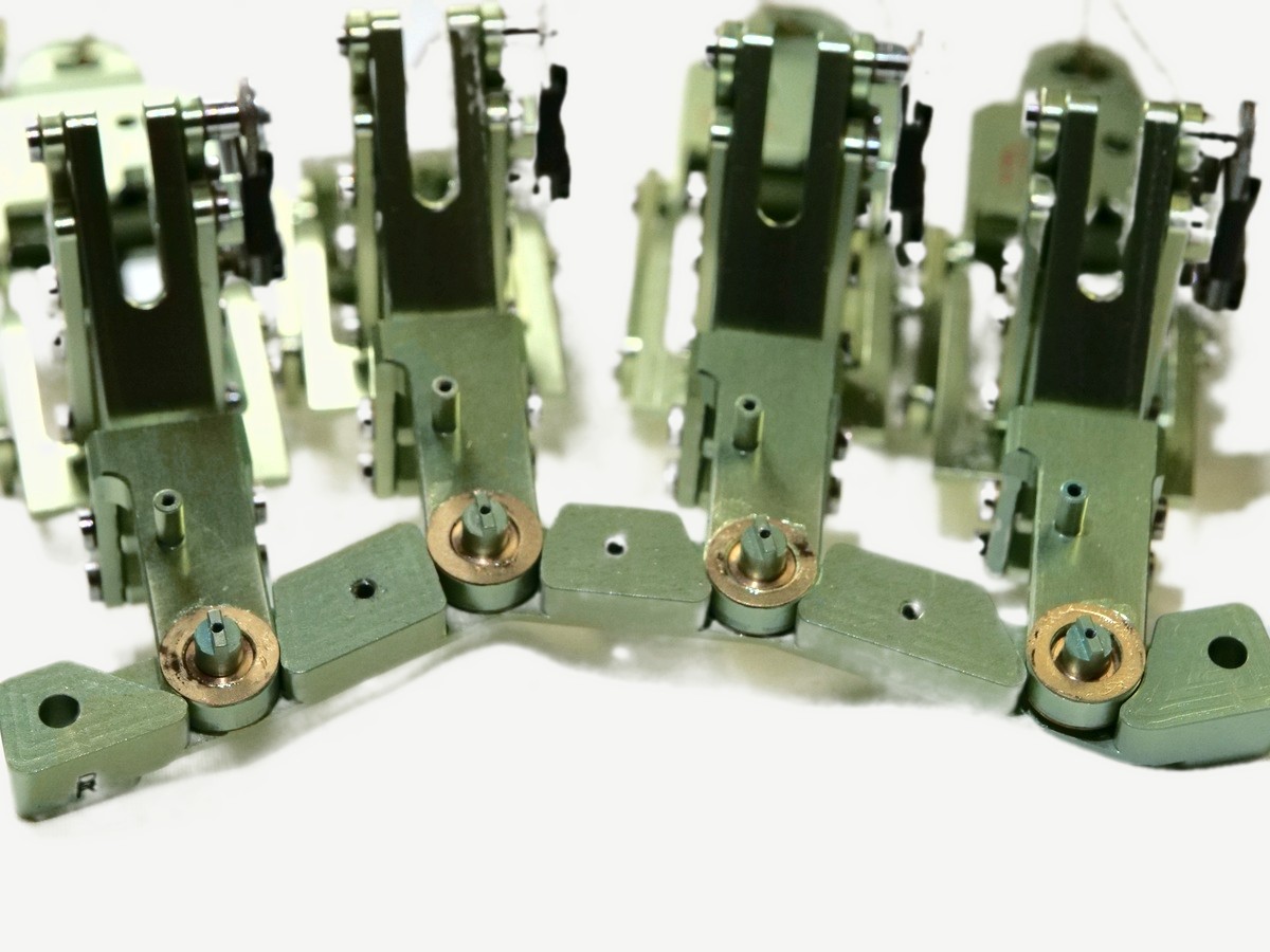
Print the parts

  1. Download the 3MF files from the 3D-printed parts table in the Bill of Materials.
  2. Open each 3MF in Bambu Studio. It already has the filament setting and print profile.
  3. Print every part in PLA: green for the thumb tops, black for the rest.
  4. Remove the supports from the parts.
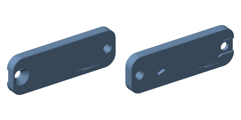
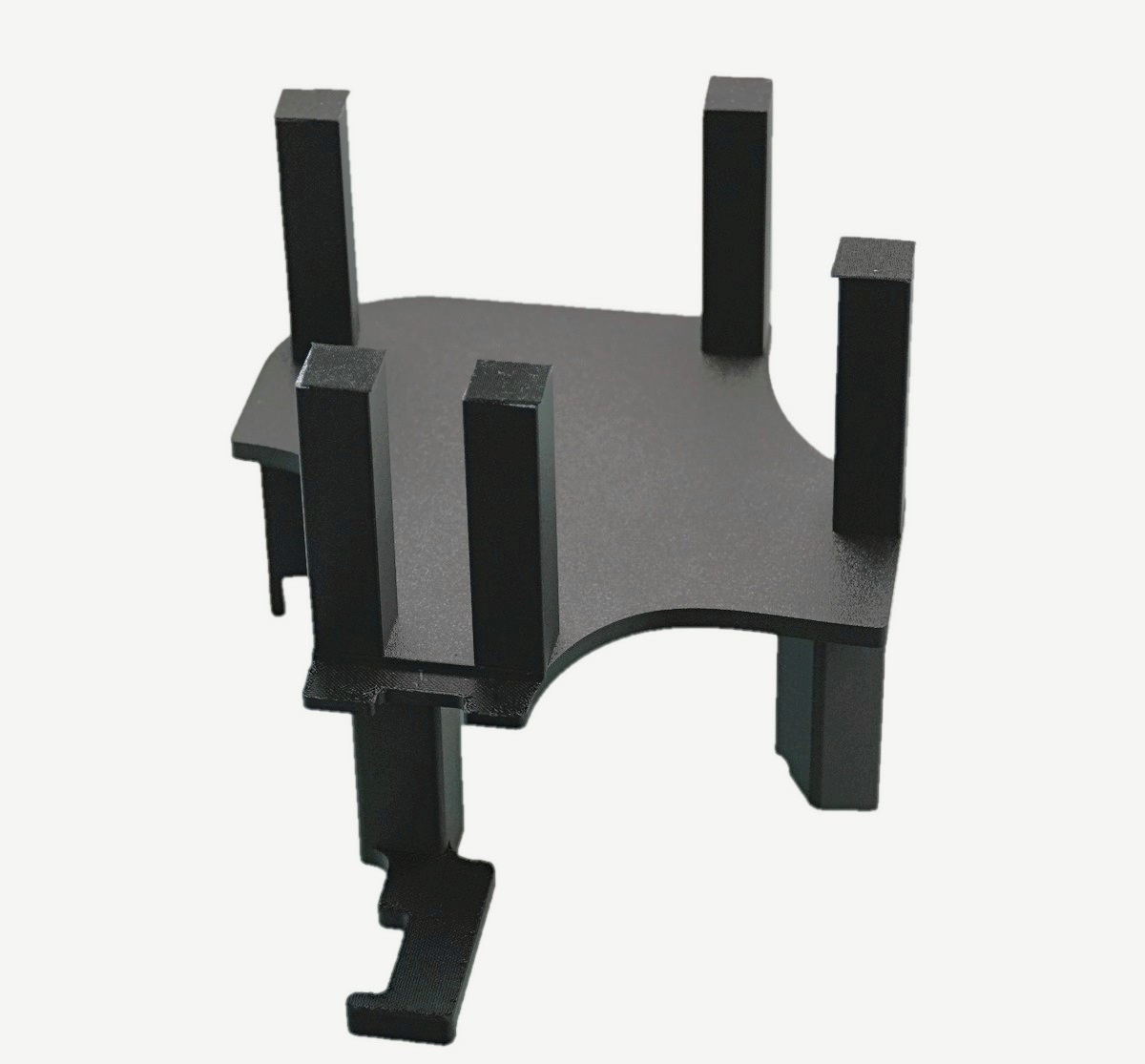
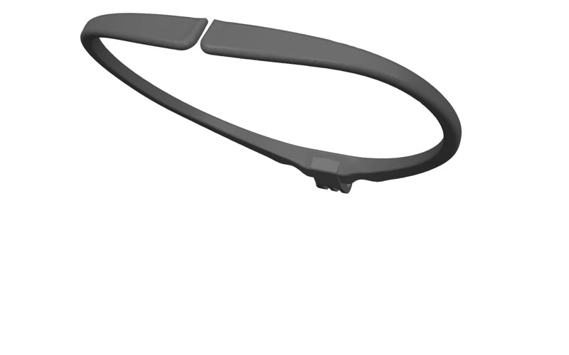
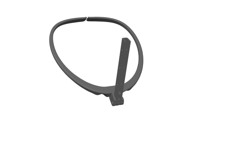
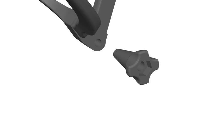
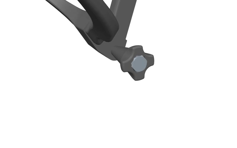
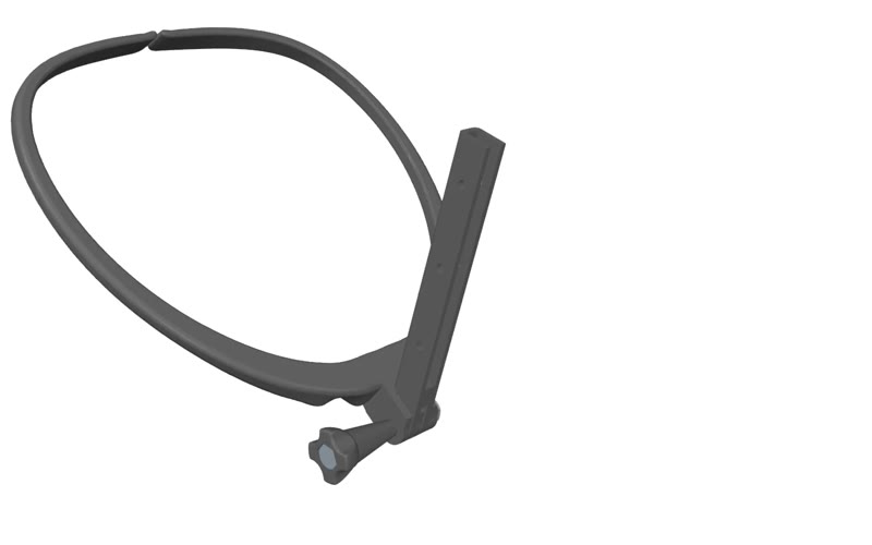
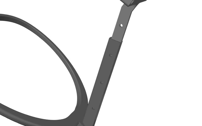
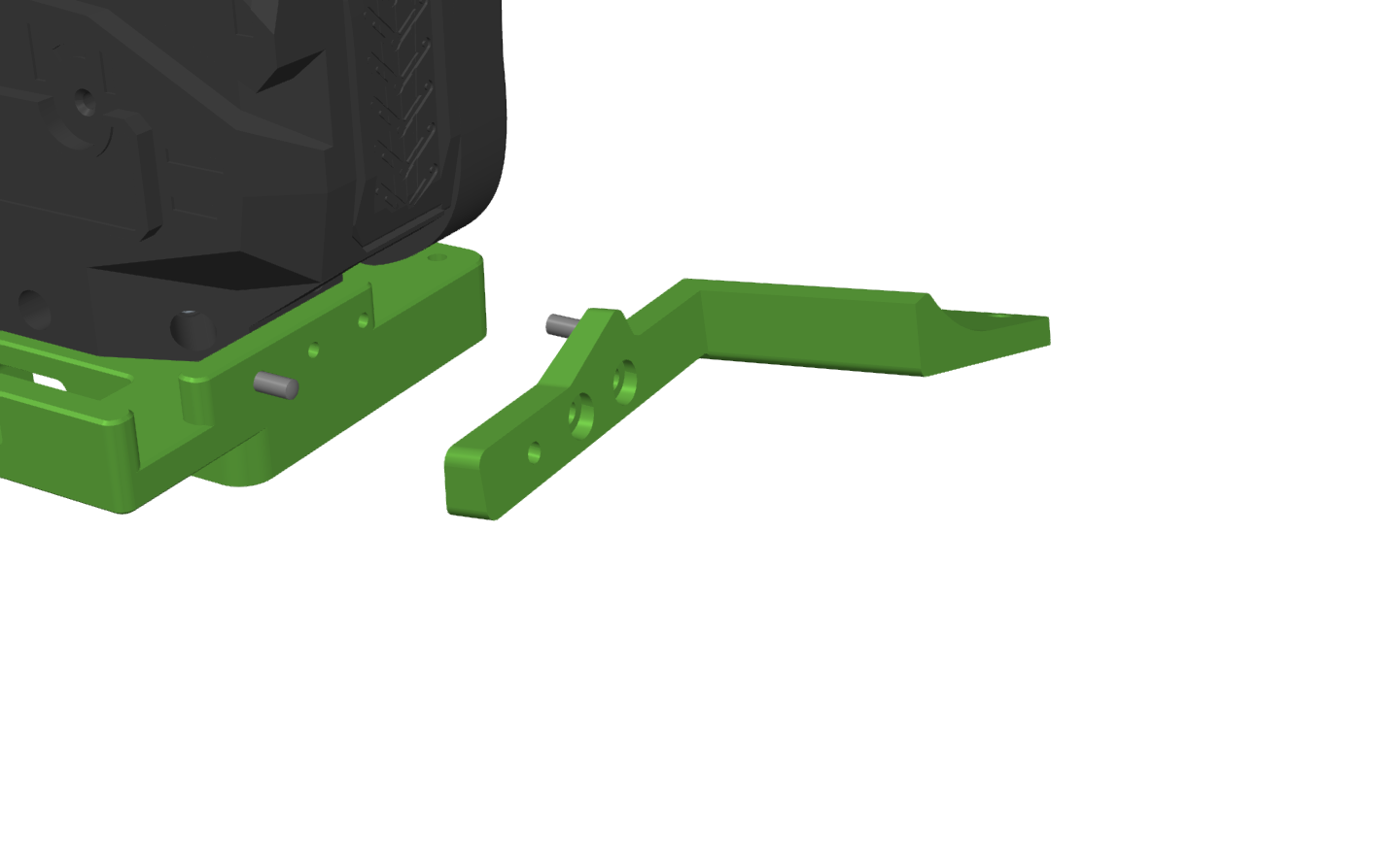
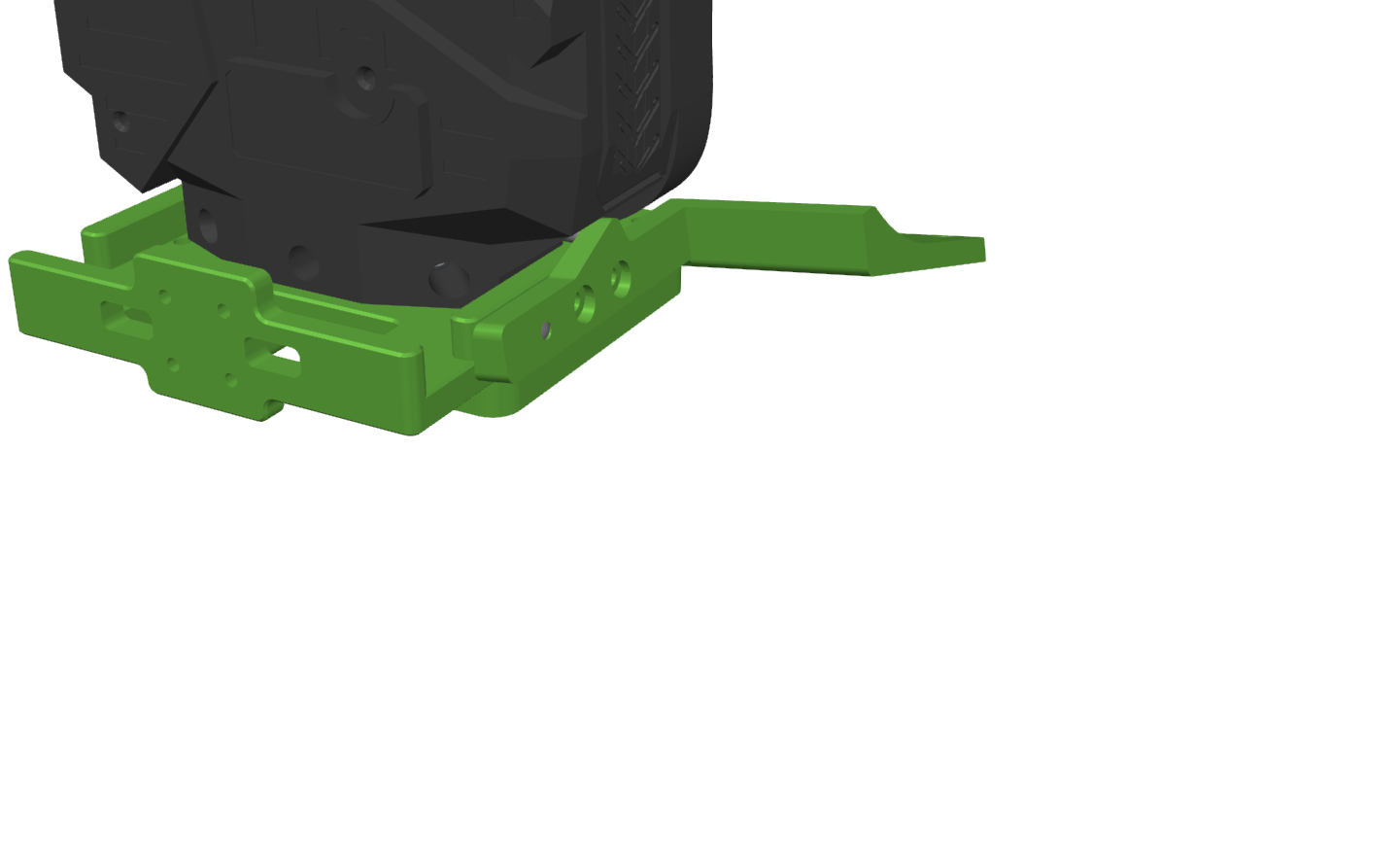
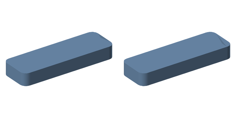
Calibration tool

1

Prepare the calibration tools

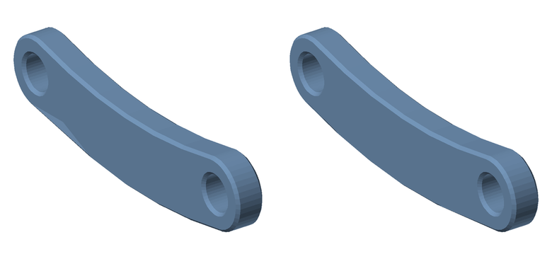
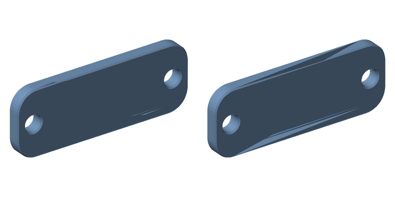
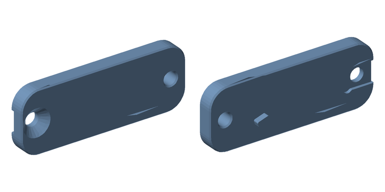
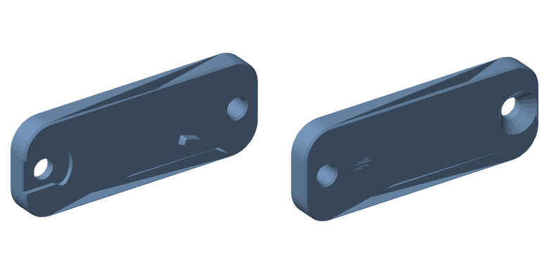
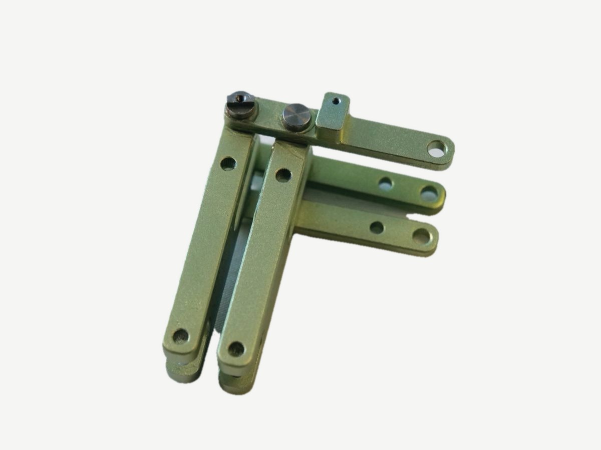
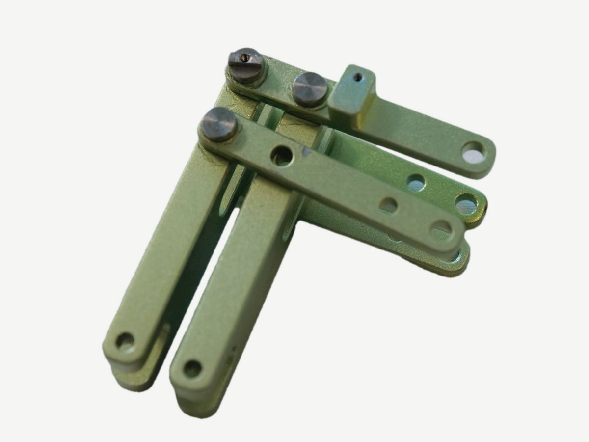
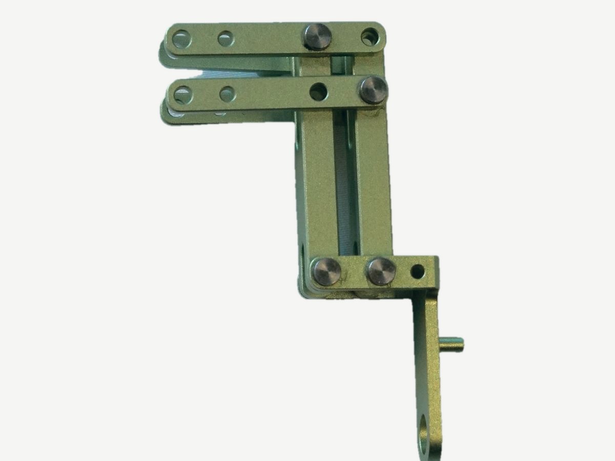
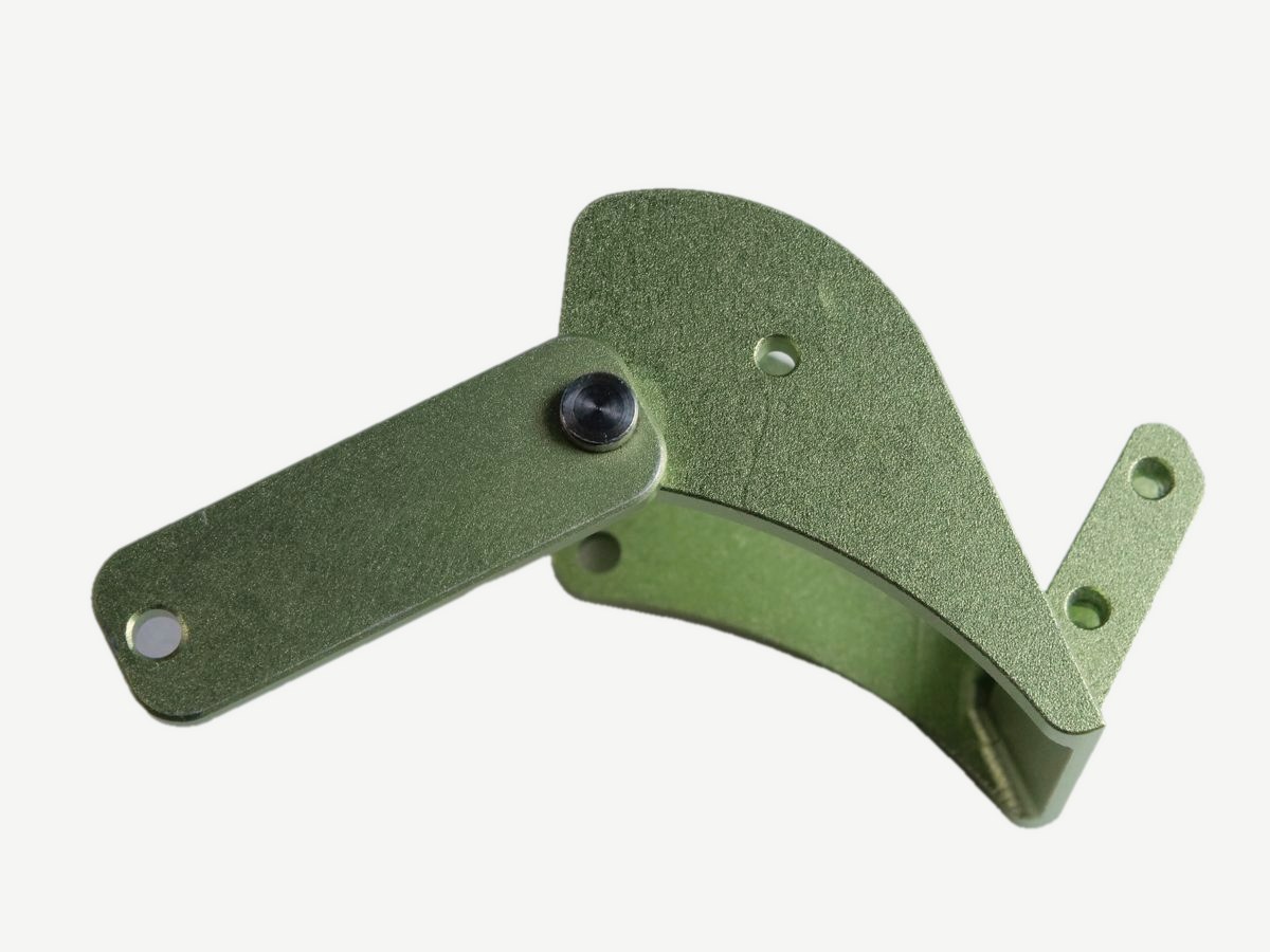
  1. Super glue the legs to the bottom of each calibration tool.
  2. Cut the grip tape to 20 x 20 mm and stick it to the bottom of each calibration tool leg.
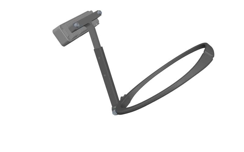
The calibration tool

Assembly reference

Which glue to use

GlueUsed onLocation
Retaining compoundSmooth top pins; adapter headsAll fingers
Red LoctiteM1.6 x 3 countersunk screw holding DU-02-06Fingertip (step 9)
Blue LoctiteStandoff screws; screw that presses down the top knuckle plateStandoffs; middle of the knuckle plates

Finger sizes

The index and ring fingers are the same size. The pinky is the smallest.

FingerRectangle lengthRectangle partLink lengthLink part
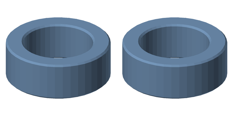
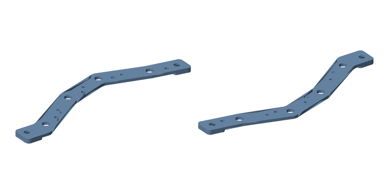
Middle30 mmDU-03-05
DU-03-06R
DU-03-06L
24 mmDU-03-04
Index / ring27 mmDU-03-02
DU-03-03R
DU-03-03L
21 mmDU-03-01
Pinky24 mmDU-03-08
DU-03-09R
DU-03-09L
18 mmDU-03-07

Sub-assemblies

Sub-assemblyHandDetails
Four-bar bridge linkLeft

Uses DU-02-01L, DU-02-02, press-fit pins and washers. Press-fit on the arbor press.

  • left knuckle bar DU-02-01L (1)
  • bridge DU-02-02 (1)
  • long smooth bar with four holes DU-02-03 (3)
  • long bar with adapter head DU-02-04L (1)
  • silver flat pins (11)
  • one silver adapter head and small gold washers
Four-bar bridge linkRight

Uses DU-02-01R, DU-02-02, press-fit pins and washers. Press-fit on the arbor press.

  • right knuckle bar DU-02-01R (1)
  • bridge DU-02-02 (1)
  • long smooth bar with four holes DU-02-03 (3)
  • long bar with adapter head DU-02-04R (1)
  • silver flat pins (11)
  • one silver adapter head and small gold washers
Fingertip (index, middle, ring or pinky)Right

Uses DU-03-10R and DU-03-09R. The reference image omits the silver circular adapter piece.

  • right fingertip DU-03-10R (1)
  • smooth small bar DU-03-09R (1)
  • small encoder bar with hard stop (1)
Fingertip (index, middle, ring or pinky)Left

Same as right, using the left-hand parts. Make sure the pieces are for the left hand.
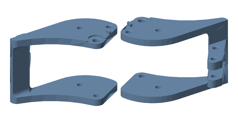
Add sensorsBoth

See Sensor assembly.

Assembly instructions

Grease the washers and press-fit with the matching DU-TOOL; colored dots show the glue.

FingersSteps 1–10

Assembly animation Fingers · steps 1–10 (3 min 1 s)

Press-fit tool placement

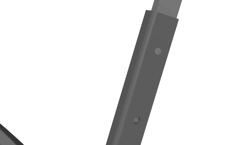
Press-fit tool placed in the link, seen from above
Press-fit tool placed in the link, seen from the side
Press-fit tool placed in the fingertip, seen from another angle
Press-fit tool in the fingertip with the links crossing over it
Press-fit tool in the fingertip, seen from the side
Press-fit tool placed in the fingertip
1

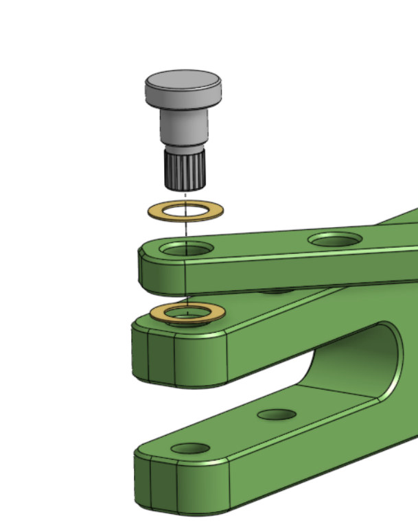
Grease the washers

  1. Apply grease to the washer.
  2. Insert the pin into the top hole of the link.
  3. Grease another washer and place it under the pin.

Note Grease every washer lightly, just enough to coat it.

Grease the washers
2

Press-fit the first pin

Retaining compound
  1. Press-fit tool placed in the link, seen from above
    Press-fit tool placed in the link, seen from the side
    Put DU-TOOL-03 between DU-02-03 and DU-02-02.
  2. Align the smooth top pin with the holes and press-fit.
Press-fit the first pin
3

Attach the second DU-02-04 link

Retaining compound
  1. Press-fit a smooth top pin to join the second DU-02-04 link.
  2. Repeat on the second set of holes for the next link.
  3. Only have two pins diagonal from each other.

Note Right hand: non-encoder link on the left. Left hand: on the right.

Attach the second DU-02-04 link
4

Attach the encoder link

Retaining compound
  1. Attach the DU-02-04 encoder link to the top hole of DU-02-02.
  2. On the second bar, repeat steps 1 and 2 on the second hole.

Note Be sure to attach the link only on the second bar with the smooth top.

Attach the encoder link
5

Attach the adapter head pin

Retaining compound
  1. Attach DU-02-04 to DU-02-02 with an adapter head pin.
  2. Follow steps 1 to 3 to attach the second DU-02-03 link.

Note Attach the adapter head last.

Attach the adapter head pin
6

Attach the knuckle part

Retaining compound
  1. Place washers on the openings at the ends of the bars.
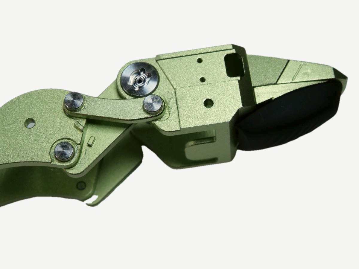
  2. Place DU-02-01 on top, aligning the washers with the holes.
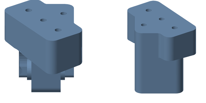
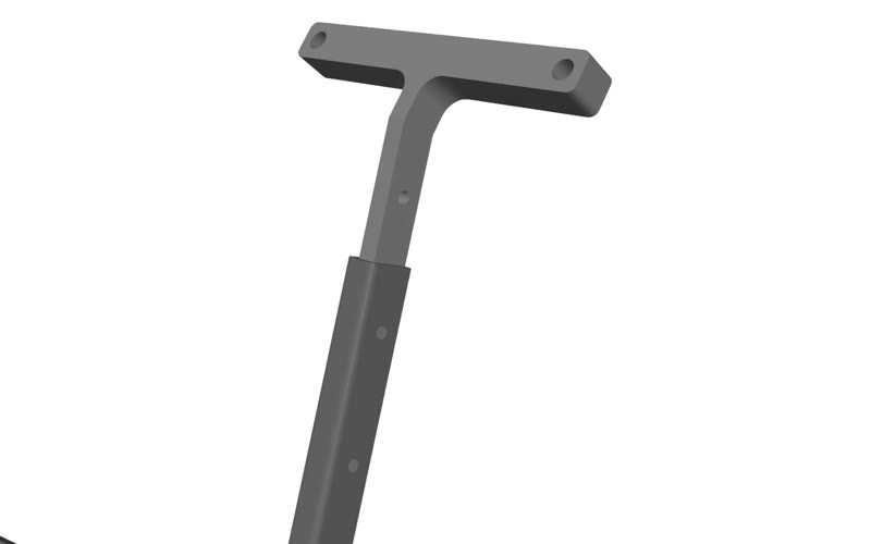
  3. Press-fit tool placed in the link, seen from the side
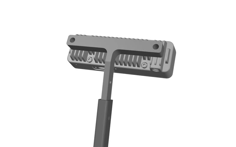
    Put DU-TOOL-03 in the bar notch, then press-fit the smooth top screws. Repeat on the other side.
Attach the knuckle part
7

Attach the DU-03-02 link

Retaining compound
  1. Place DU-03-02 (5)(8) onto DU-02-05 on the non-encoder side.
  2. Pass a smooth top screw and washer through DU-03-02.
  3. Press-fit tool placed in the link, seen from above
    Press-fit tool placed in the link, seen from the side
    Washer between the links, DU-TOOL-03 in the middle link, then press-fit.

Note Refer to finger sizes here.

Attach the DU-03-02 link
8

Attach the rectangular link

Retaining compound
  1. DU-TOOL-02 placed in the fingertip, seen from the side
    Insert DU-TOOL-02 into the DU-03-10 fingertip.
  2. Place a washer on the opening, then the DU-03-02 rectangular link on top.
  3. Align the holes.
  4. Follow the press-fit procedure.
  5. DU-TOOL-01 placed in the fingertip
    Follow the same steps to attach DU-03-06, using DU-TOOL-01.
Attach the rectangular link
9

Attach DU-02-06

Loctite
  1. Attach DU-02-06 and secure it with an M1.6x3 countersunk screw.
Attach DU-02-06
10

Attach the elbow link

Retaining compound
  1. Press-fit tool placed in the fingertip, seen from another angle
    Press-fit tool in the fingertip with the links crossing over it
    Encoder side: place DU-03-01 (4)(7) at the opening, add DU-TOOL-01.
  2. Follow the press-fit protocol.
Attach the elbow link

ThumbSteps 11–17

Assembly animation Thumb · steps 11–17 (1 min 55 s)
11

Join DU-04-01 to DU-04-02

Retaining compound
  1. On the non-encoder side, press-fit DU-04-01 to DU-04-02 with a smooth top pin.
  2. Use washers only between the pin and DU-04-02.
  3. Then press-fit the encoder side with an adapter head pin.

Tip the encoder attachment is the tube sticking out. Every time you see it, use an adapter head pin in that area.

Join DU-04-01 to DU-04-02
12

Join DU-04-02 to DU-04-03

Retaining compound
  1. Non-encoder side: press-fit DU-04-02's long thin end to DU-04-03.
  2. Use a smooth top pin; repeat on the other side with an adapter head pin.
Join DU-04-02 to DU-04-03
14

Repeat on the encoder side

Retaining compound
  1. Repeat on the encoder side with adapter head pins.
Repeat on the encoder side
16

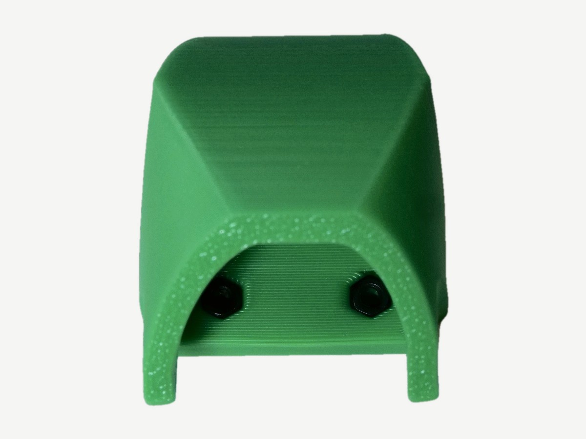
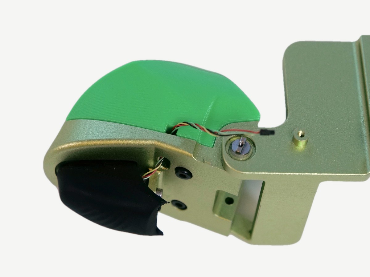
Attach the thumb cover nut

  1. Insert the M2 nut, then attach the printed thumb cover.
Attach the thumb cover nut
17

Screw on the thumb cover

  1. Screw on the cover with an M2x5 socket cap screw.
  2. Route the 102 mm ENC to SEN wire through the side hole.
Screw on the thumb cover

PalmSteps 18–20

Assembly animation Palm · right-hand assembly (2 min 15 s)

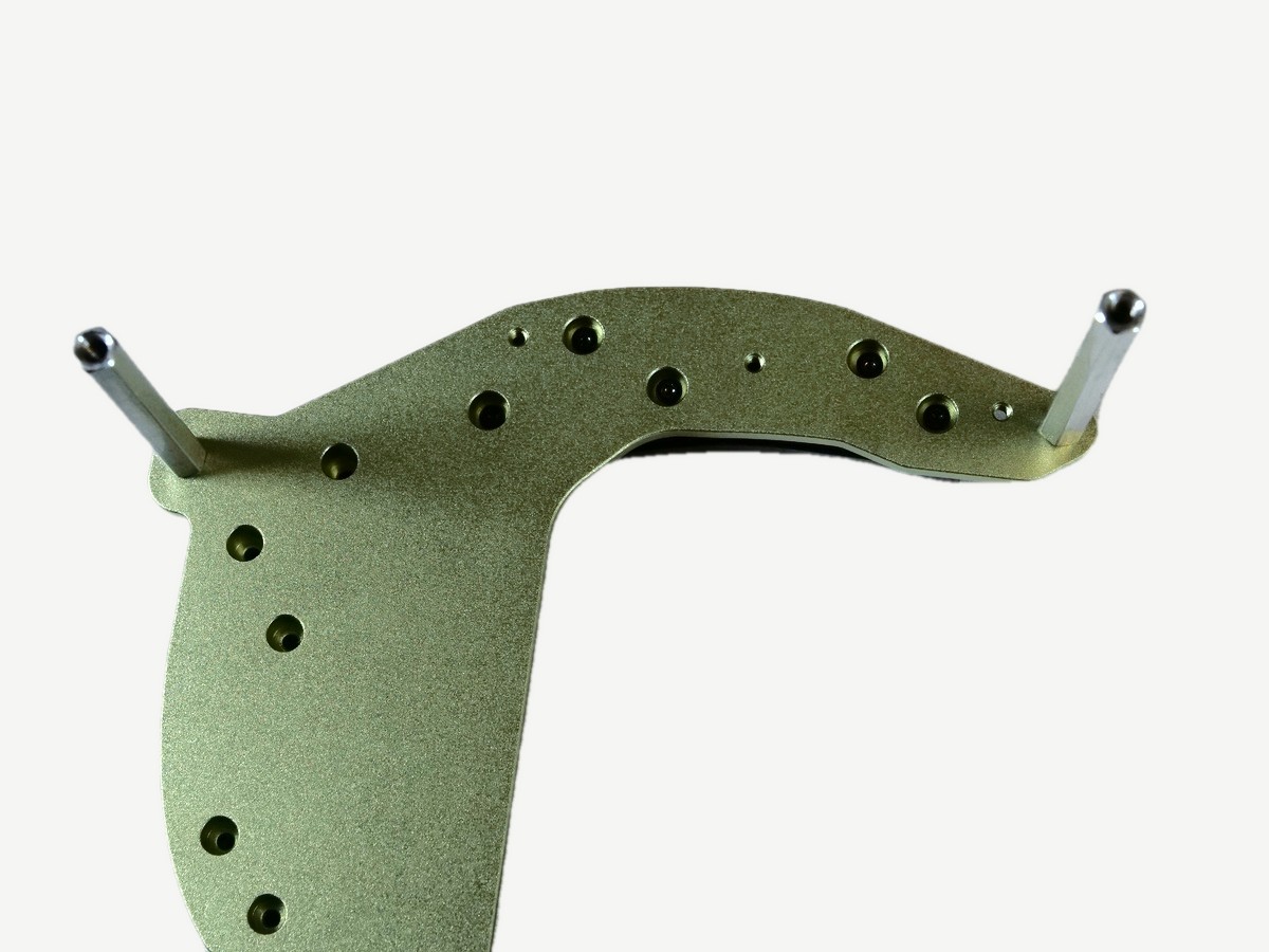
Note The palm tactile sensors are not used for the policy, so they are optional. You can screw on the tactile sensors or glue on the 3D-printed versions instead.

18

Glue and orient the palm sensors

  1. Dab super glue onto the mini stands of the palm plate.
  2. Align a palm sensor to the holes and press down.
  3. Repeat steps 1 and 2 for the other palm sensor.
  4. Place the wider ends of the sensors next to each other.
Palm sensors with the wider ends next to each other
19

Screw in the tactile palm

If you are using the tactile palm, screw it in with M2x6 screws.

Tactile palm screwed to the palm plate
20

Secure the standoff

Loctite
  1. Secure the standoff with an M3x8 countersunk screw.
  2. Repeat on the other end of the palm plate for the second standoff.
Secure the standoff
Both standoffs secured on the palm plate

Knuckles and finger attachmentSteps 21–27

21

Clean the surfaces

  1. Clean each knuckle hole with acetone and remove any grease.
  2. Also clean the bottom knuckle plate (DU-01-03) with acetone.
  3. Rub the surfaces with Scotch-Brite for 10 to 15 seconds.
  4. Clean with acetone again.
Clean the surfaces
22

Glue the washer pin

  1. Apply four dots of super glue on the knuckle surface.
  2. Insert a 6.0 gauge pin through the hole.
  3. Slide down a large washer, slowly twist, then apply pressure.
  4. Let the glue dry for a minute; check the washer is centered.
  5. Wipe off excess glue with acetone.
  6. Flip the knuckle over and repeat steps 1 to 5.

Note Use only a smudge of super glue at the knuckle's center hole; excess adds finger height.

Glue the washer pin
23

Insert the gold donut

  1. Insert the gold donut (DU-01-05) onto the bottom plate.
  2. Grease both washers.
  3. Grease the gold donut.
Insert the gold donut
24

Repeat on the other fingers

  1. Repeat the previous instructions on all other fingers.
Repeat on the other fingers
25

Press down the top knuckle plate

  1. Take the top knuckle plate (DU-01-04) and press down.
Press down the top knuckle plate
26

Lock the knuckle plates

Loctite
  1. Lock the knuckle plates with M2x5 Phillips countersunk screws.
Lock the knuckle plates
27

Check for gaps and attach the plate

Loctite
  1. Ensure no gap is visible after screwing the plate.
  2. Screw the plate to the standoffs with M3x12 countersunk screws.

Note Check for up-and-down slop in the knuckle joint. It should only move side to side.

Check for gaps
Attach the plate to the standoffs

Sensor assembly

Fingertip sensorSteps 1–5

1

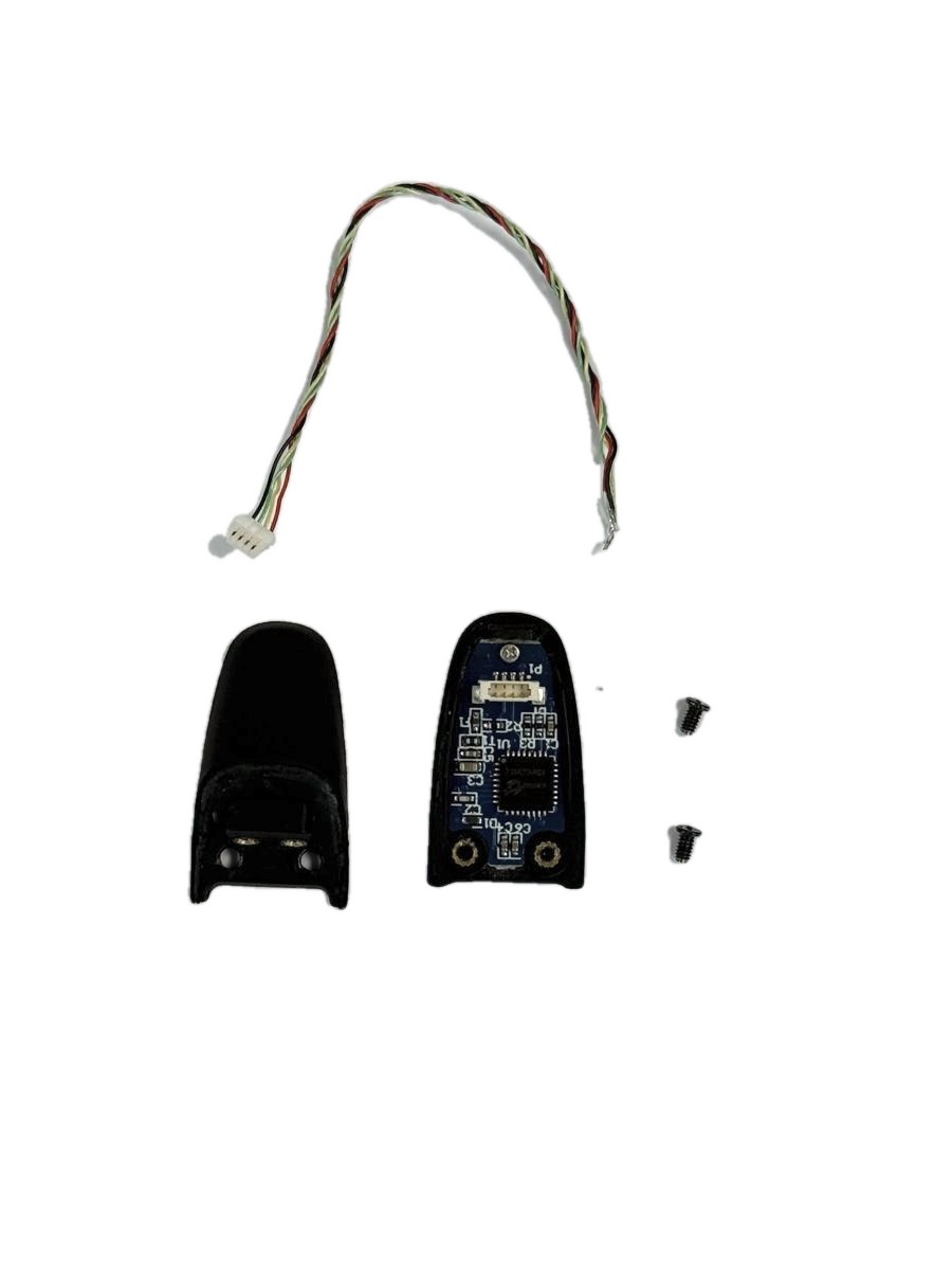
Separate the sensor

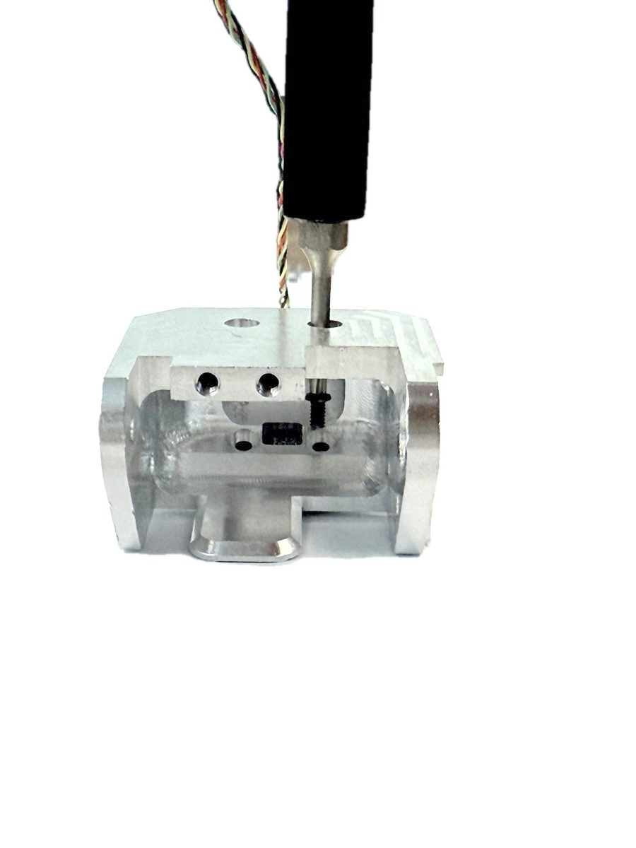
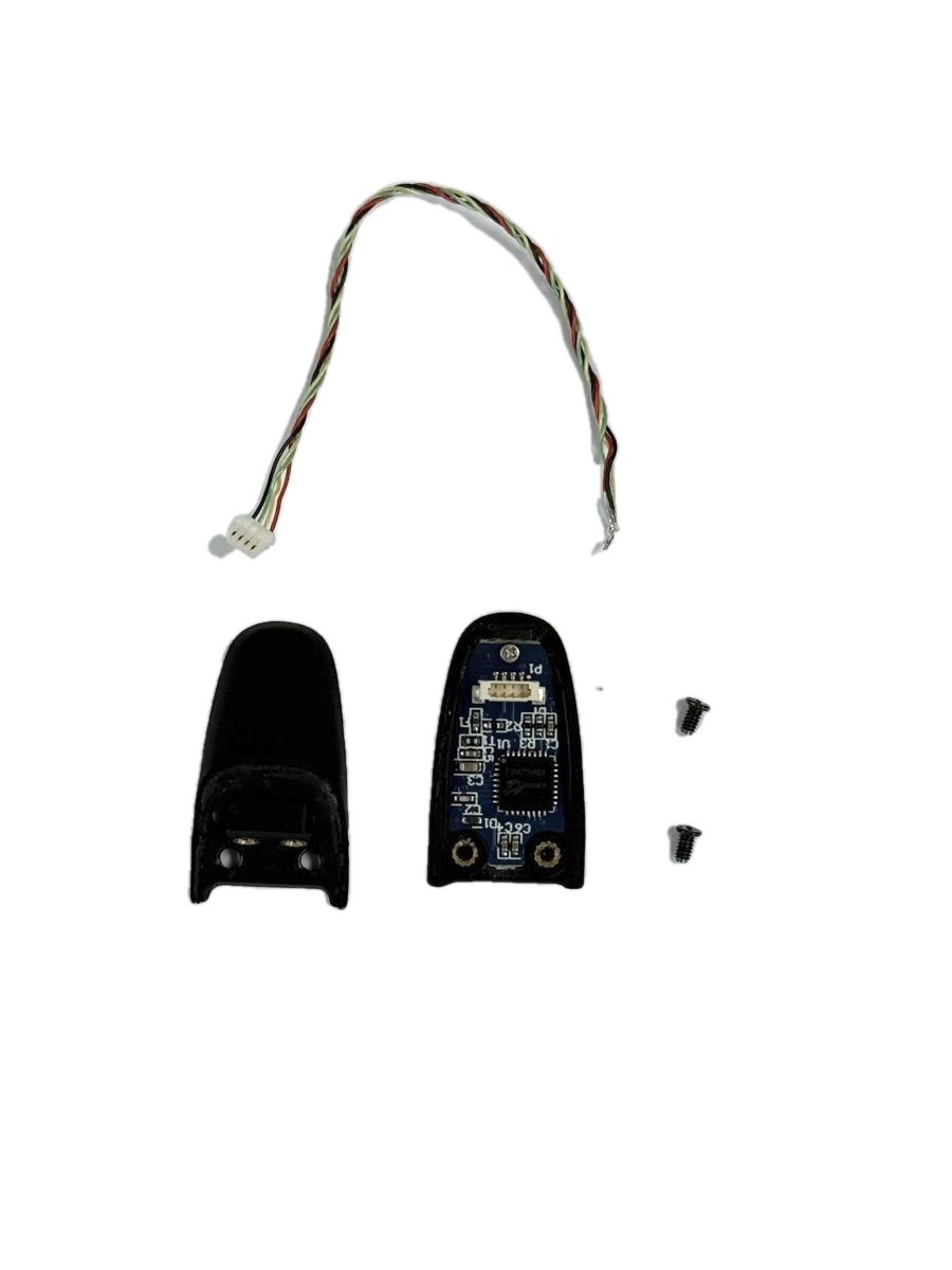
Unscrew the two black screws and separate the top part of the sensor. Keep the two black screws, you will use them later.

Take out the wire that initially comes with the sensor.

Separate the sensor
2

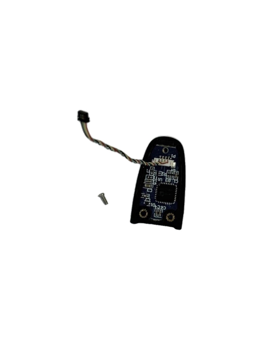
Attach the wire

Unscrew the silver screw on the top of the sensor chip. Use a 50 mm encoder-to-sensor wire and attach its white end to the sensor.

Attach the wire
3

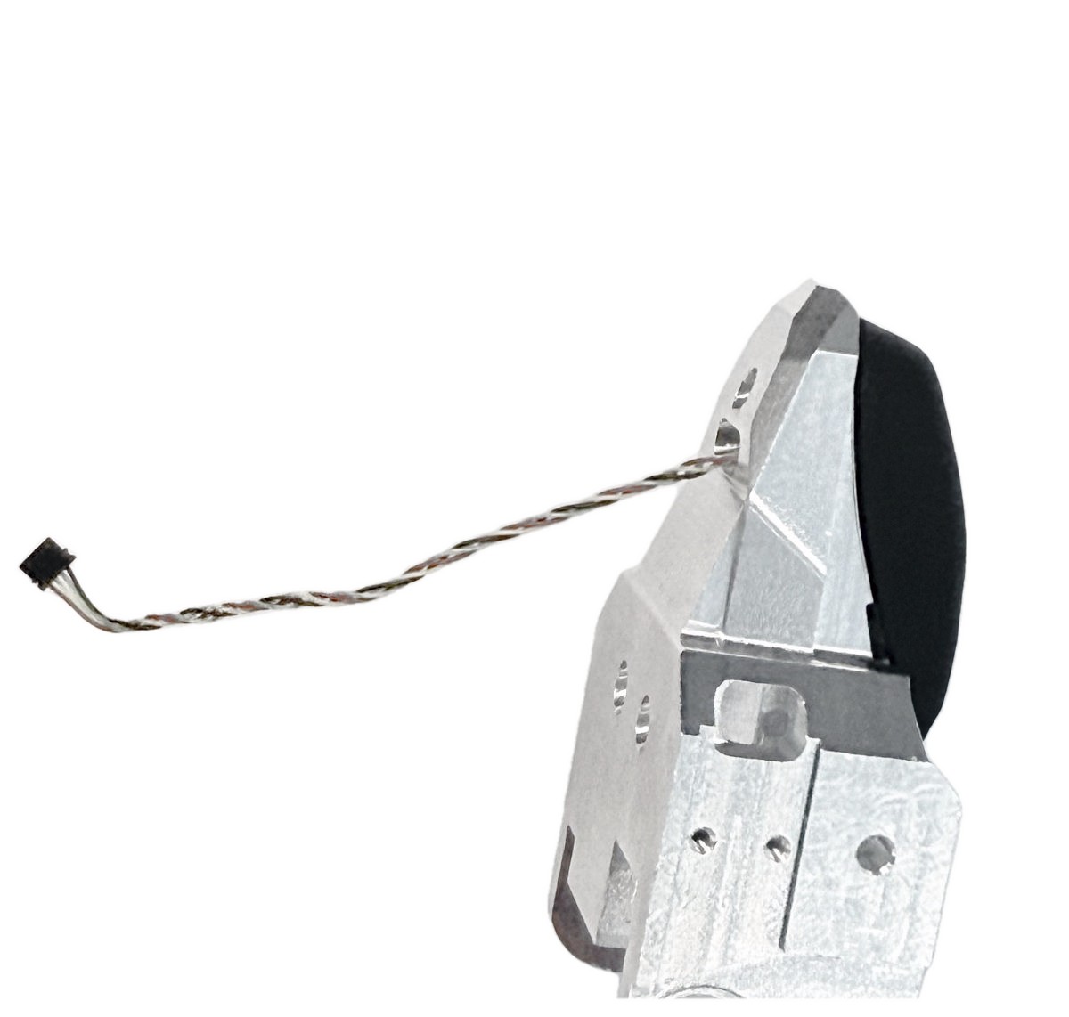
Place the chip

Place the chip on the metal fingertip by inserting the wire through the rectangular center hole first.

Place the chip
4

Fasten the top screw

Use an M1.2 x 4 screw to fasten the sensor to the metal tip through the hole on the top, above where the wire comes out.

Fasten the top screw
5

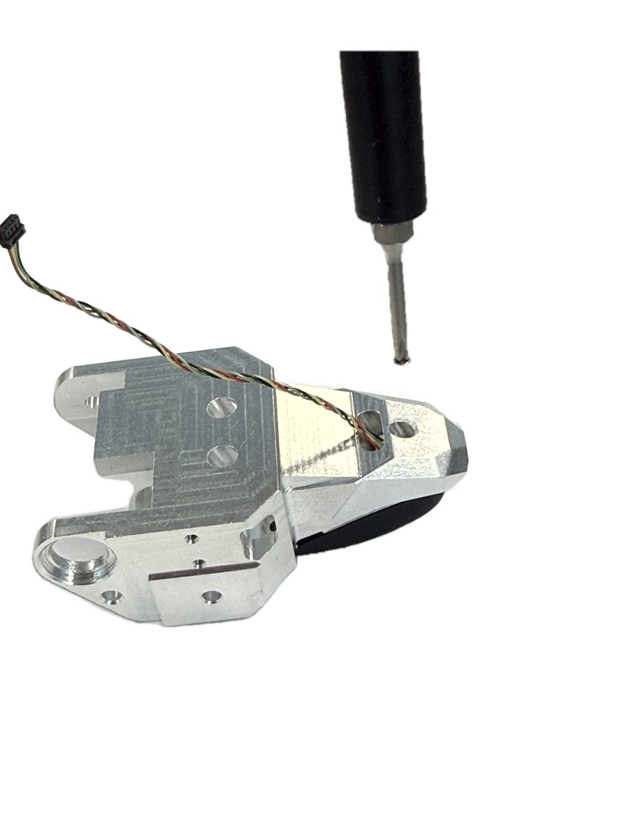
Secure with black screws

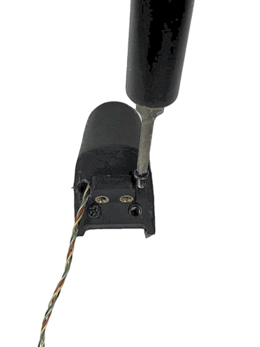
Using the black screws from step 1, insert the two screws through the metal fingertip holes to secure the sensor.

Secure with black screws

Fingertip grip tapeStep 1

1

Cut the grip tape

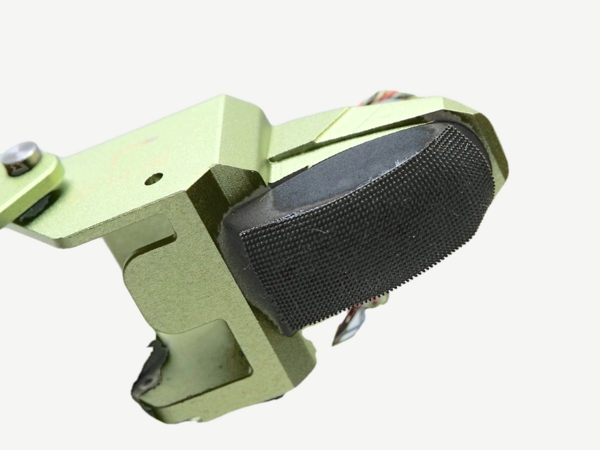
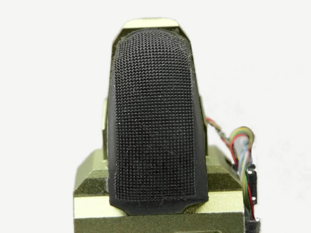
Cut the grip tape to 12 x 25 mm to fit the fingertip tactile sensor.

Fingertip tactile sensor with the grip tape on, seen at an angle
Fingertip tactile sensor with the grip tape on, seen from the front

Thumb sensorSteps 1–4

1

Take apart the sensor

Take apart the sensor by following step 1 of the finger sensor assembly. Hold onto the cap of the sensor.

Replace the wire with a 102 mm encoder-to-sensor wire.

Take apart the thumb sensor
2

Widen the cap hole

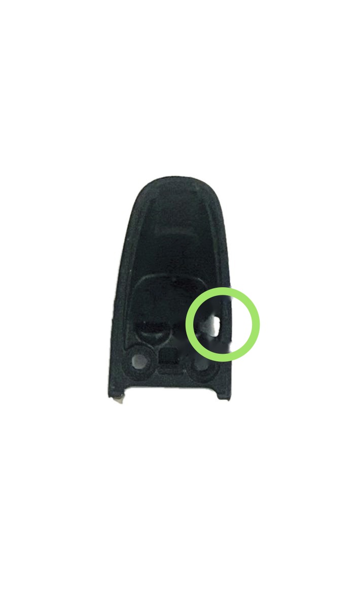
On the right-hand side of the sensor cap there is a rectangular hole where the wire goes through. Widen the hole using a Phillips screwdriver, just enough that the other end of the wire can slip through.

Note Do not unscrew the silver screw on the top of the chip.

Widen the rectangular hole in the sensor cap
3

Attach the wire and cap

Attach the 102 mm encoder-to-sensor wire and put the black end through the cap.

Secure the cap using the two black screws from step 1.

Secure the cap with the two black screws
4

Mount the sensor on the thumb

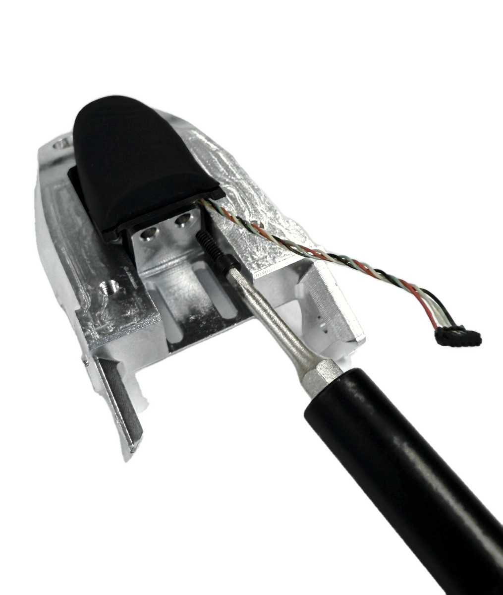
Insert the sensor onto the thumb exoskeleton, then screw it in place with M1.6 x 4 socket head screws.

Mount the sensor on the thumb exoskeleton

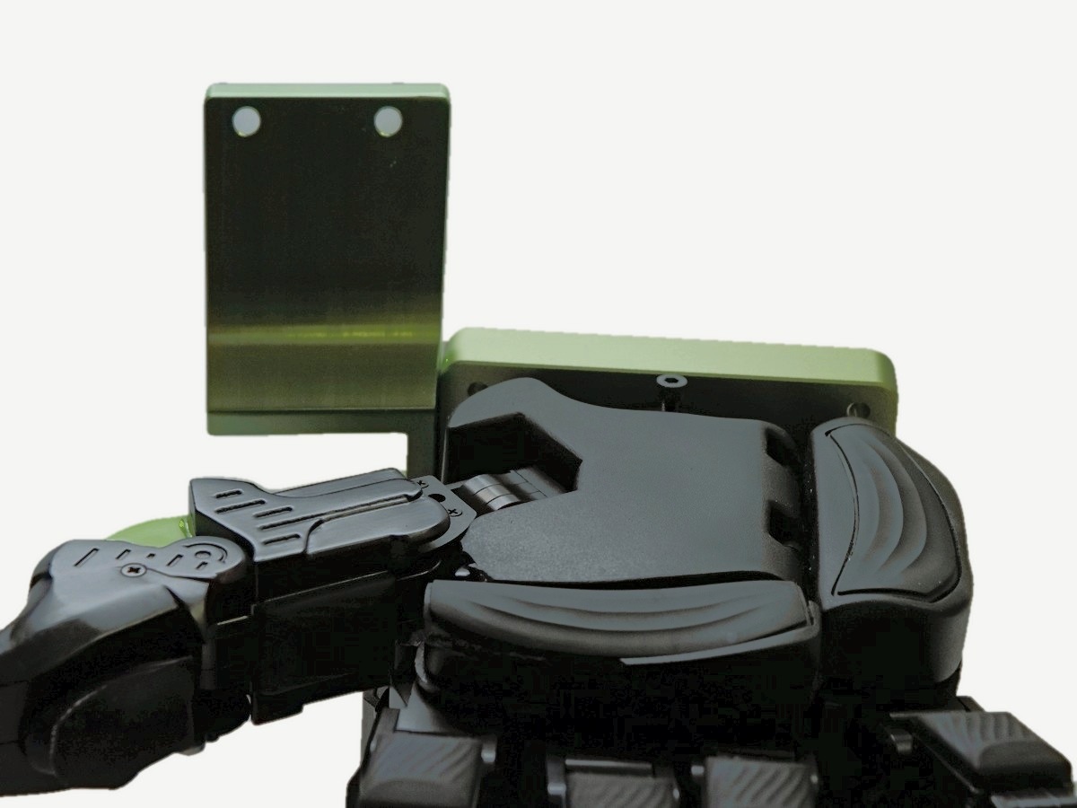
Palm mount assembly

1

Press-fit the hard stops

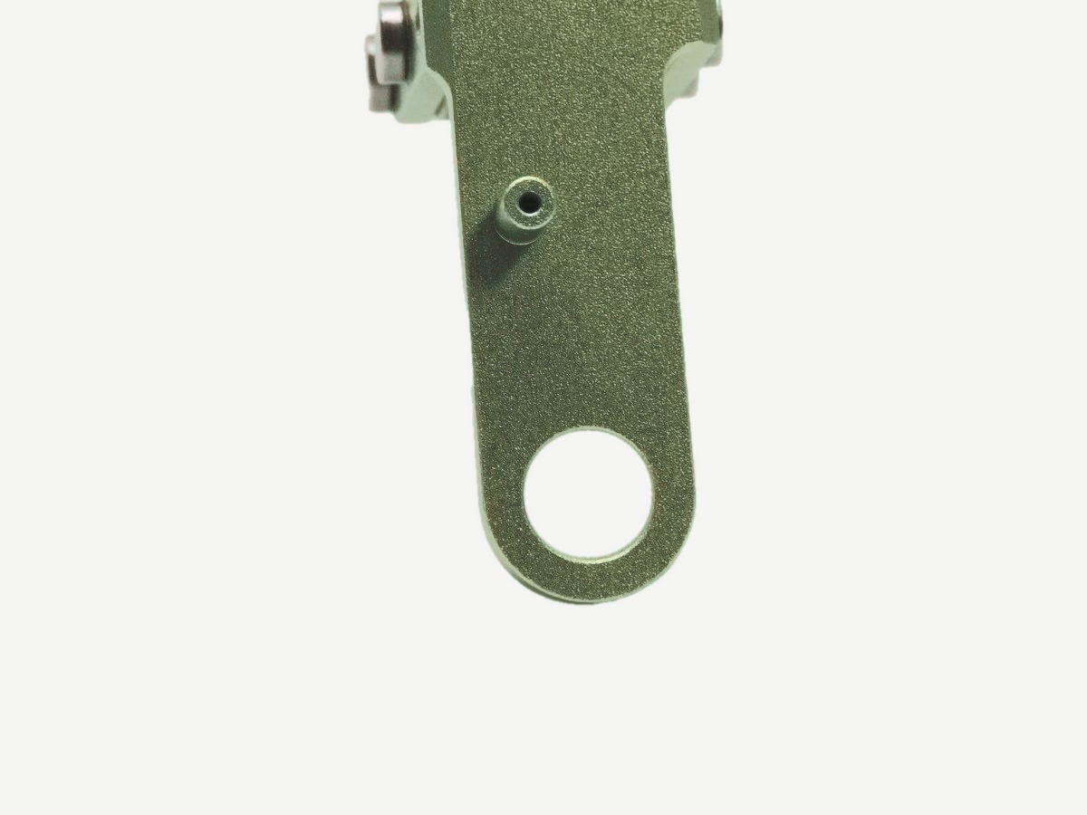
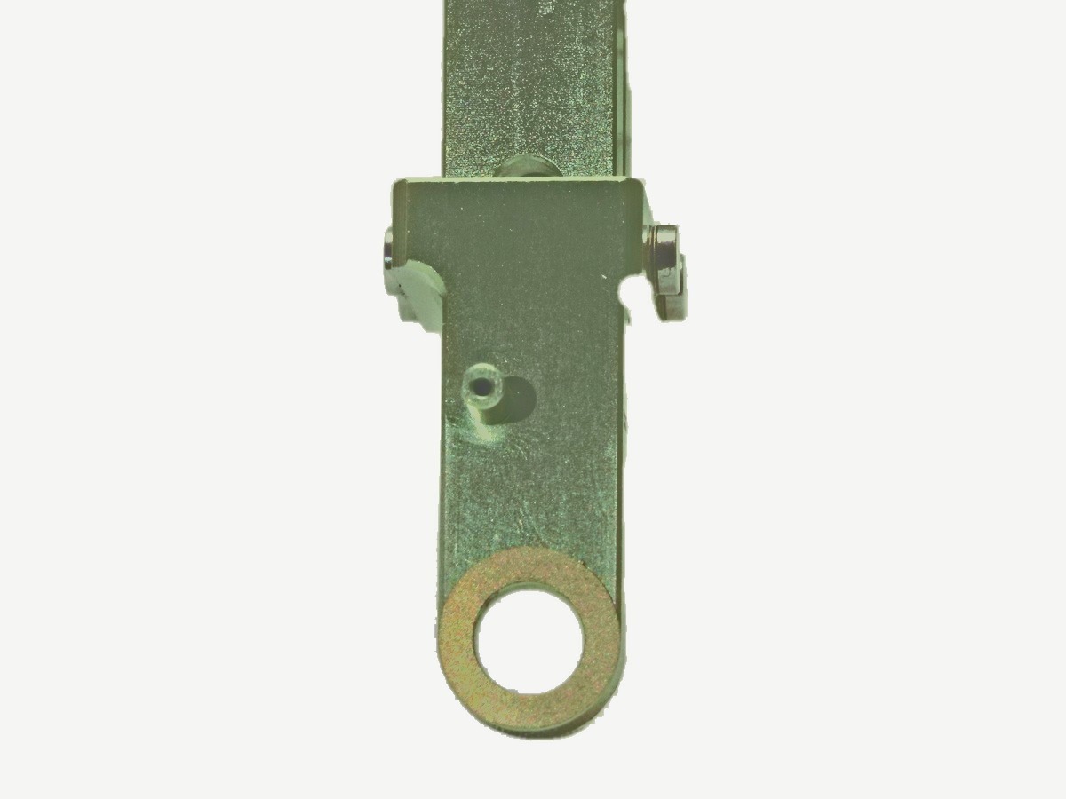
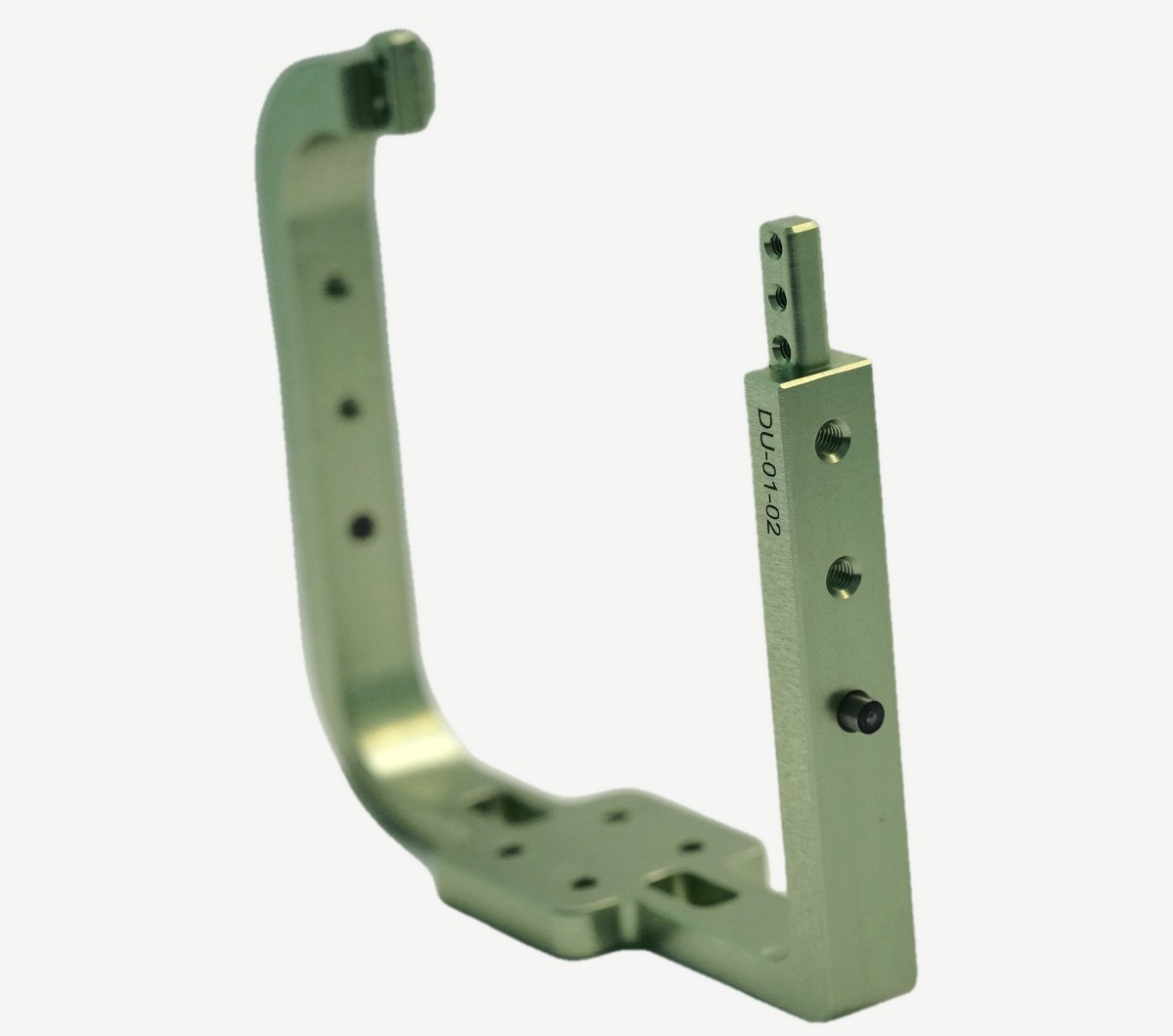
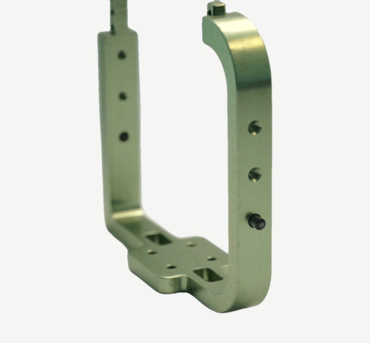
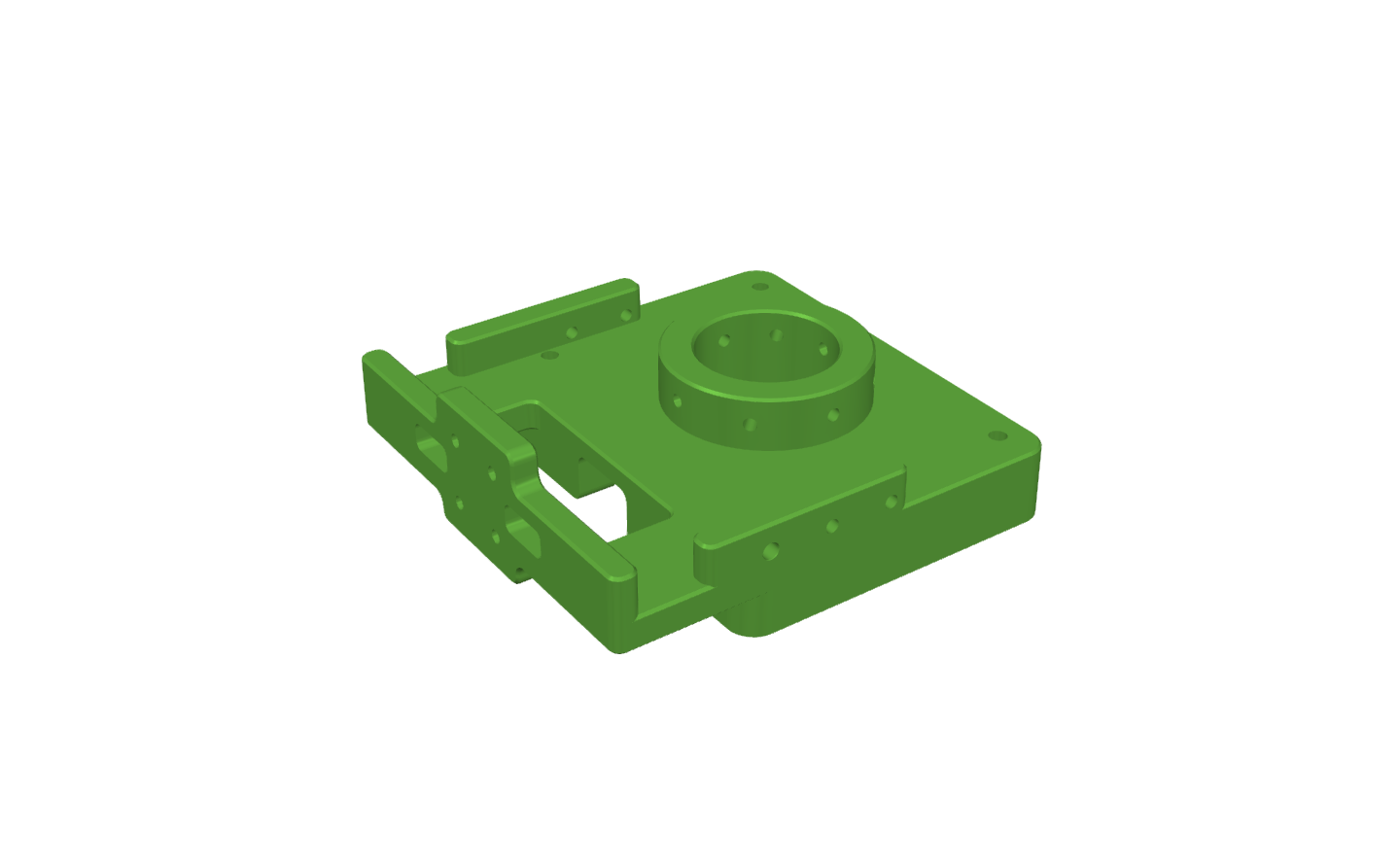
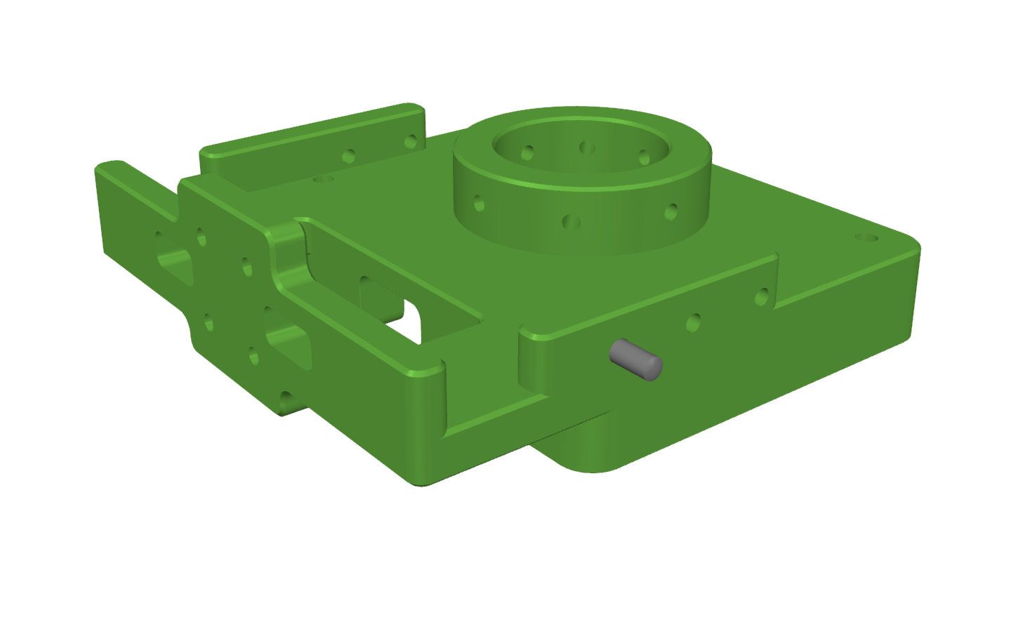
  1. Press-fit the hard stops into the palm mount (DU-01-02).

Note The rounded end of the pin goes into the hole first when you press-fit it.

The palm mount, DU-01-02, with a hard stop pressed in
The palm mount, DU-01-02, seen from the other side
2

Attach the palm mount

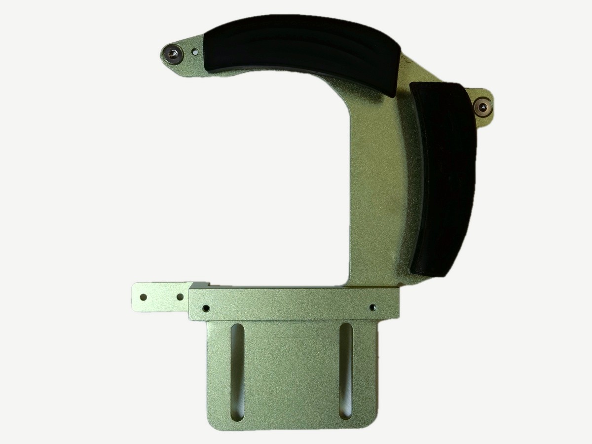
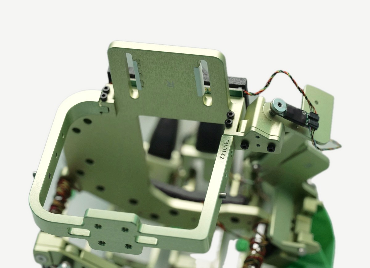
  1. Slide the palm mount into the palm plate and fasten it with four M2x6 hex screws.
The palm mount fastened to the palm plate

Camera mount assembly

1

Attach the camera mount

  1. Mount the camera mount on the back of the palm mount wall.
The camera mount
2

Install the camera

  1. Install the OAK-1W camera on the lower end of the camera mount.
The OAK-1W camera fastened to the camera mount
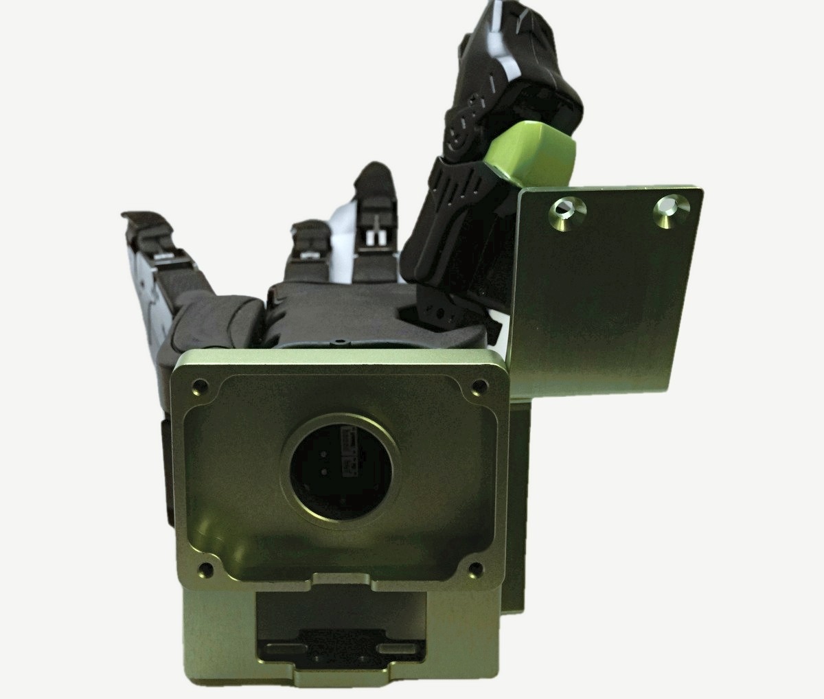
The camera mount and camera on the finished palm mount

Final assembly

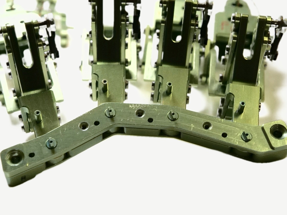
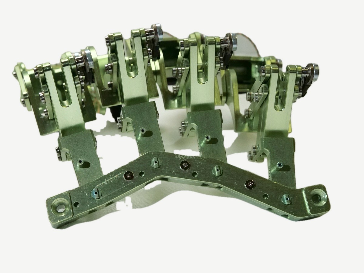
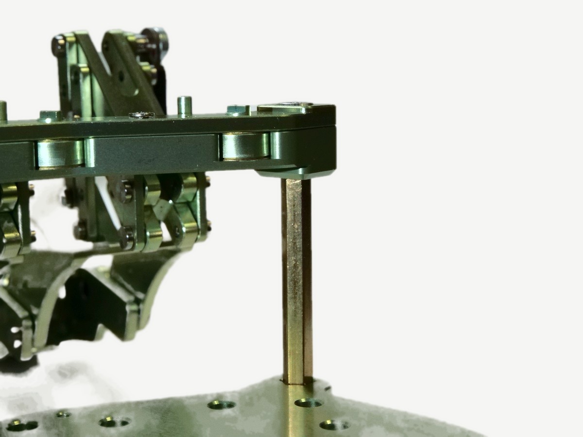
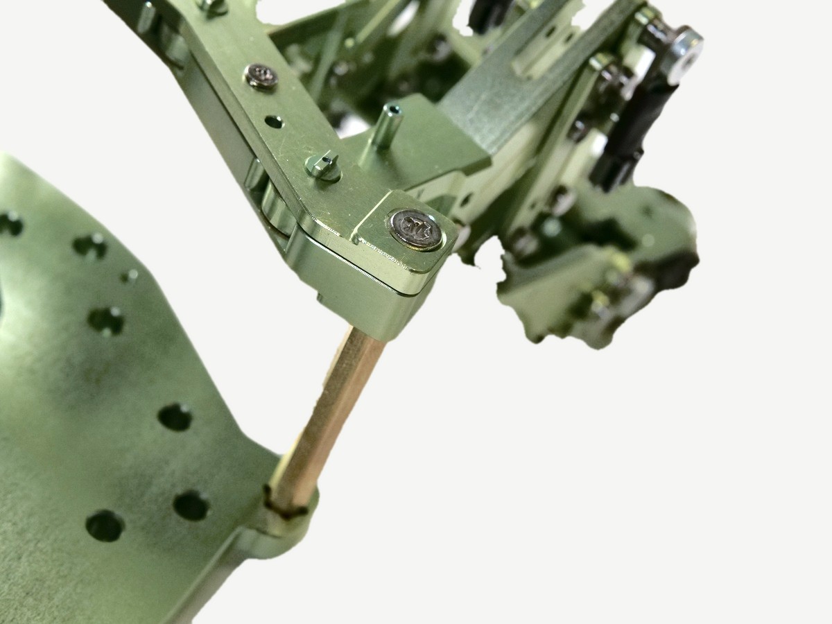
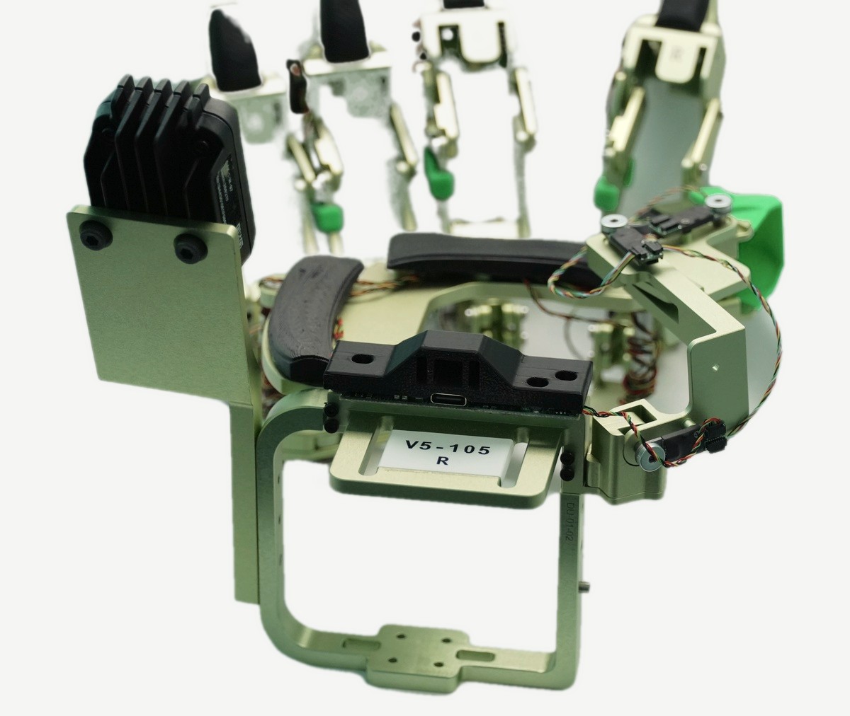
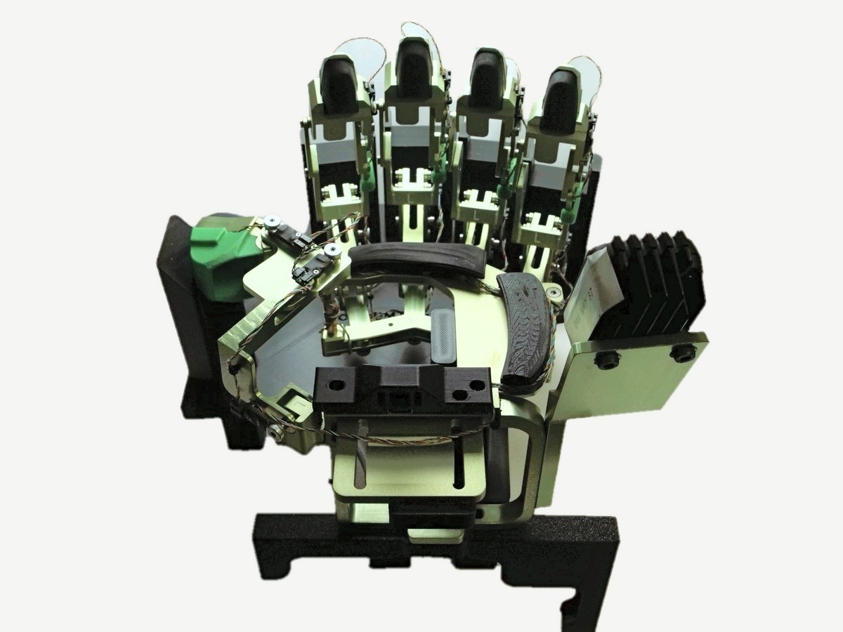
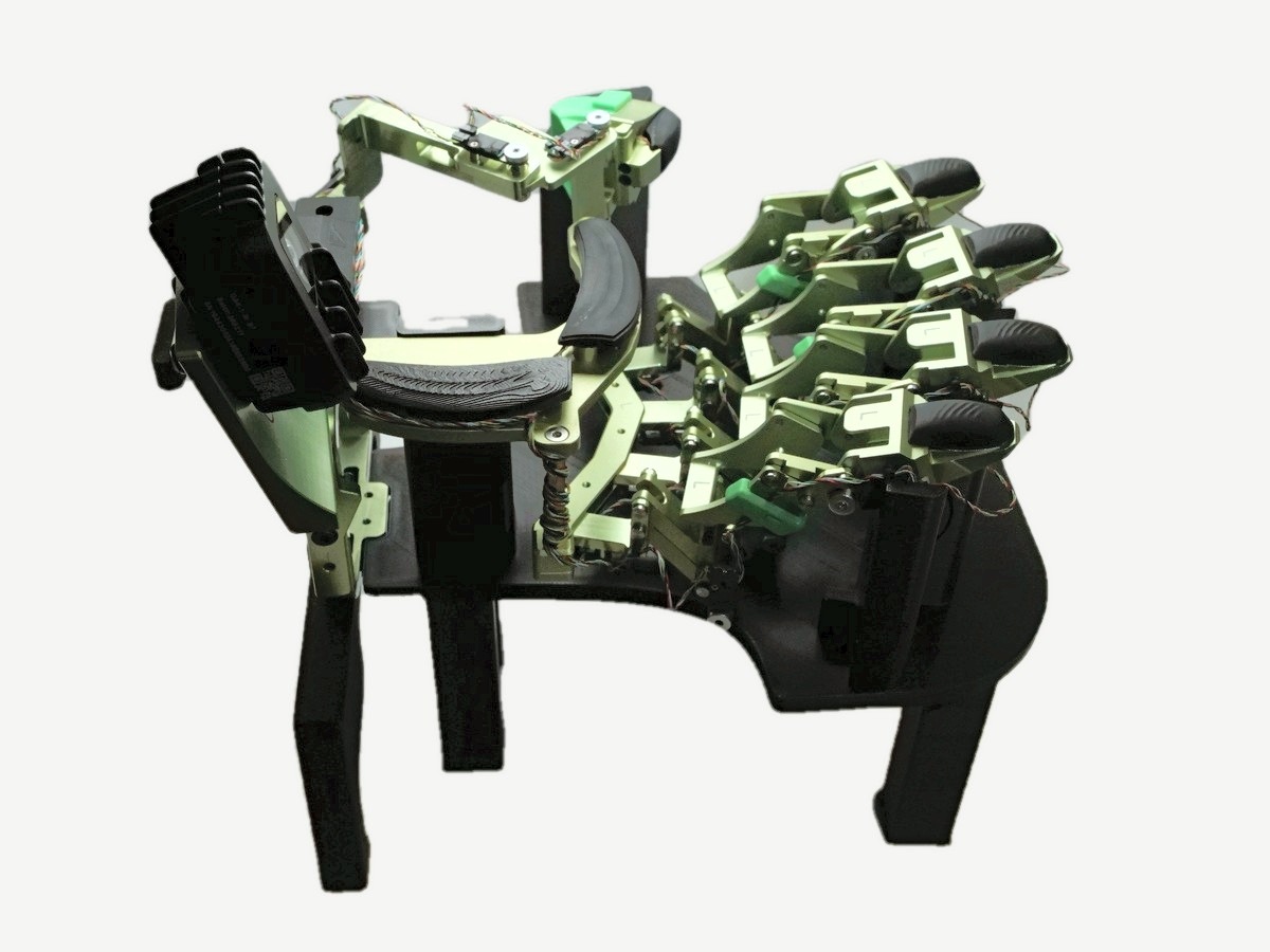
Finished exoskeleton on the calibration tool, seen from above
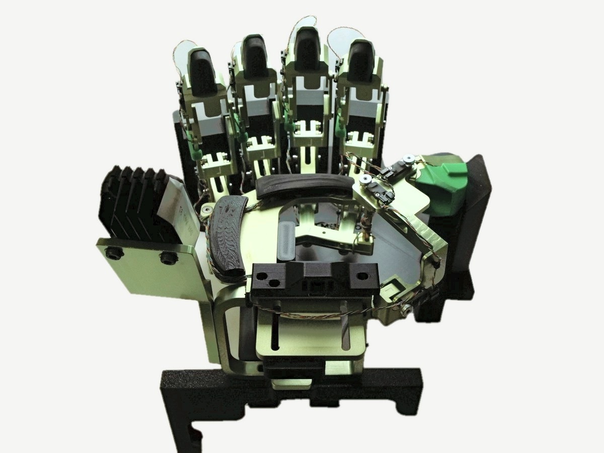
Finished exoskeleton on the calibration tool, seen from above, mirrored
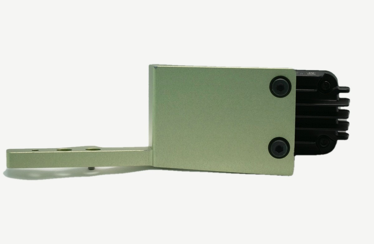
Finished exoskeleton on the calibration tool, seen from the side

Encoder and wiring

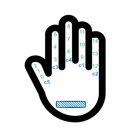
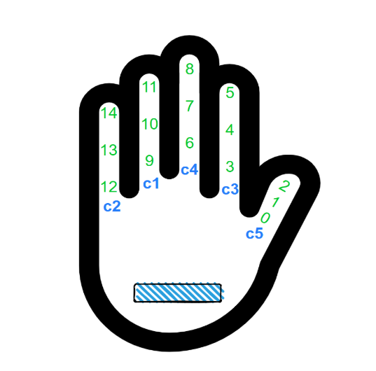
Viewed palm face up. Joint encoders are numbered 0–14 and the PCB connectors are c1–c5. The fingertip sensor is not part of the encoder count.

Wire lengths and routing

ConnectionWire typeWire lengthHandRouting and assembly notes
Fingers: between encoders (daisy chain)ENC → ENC102 mmBothConnects adjacent joint encoders
Fingers: encoders 3, 6, 9, 12 to PCBENC → ENC254 mmBothWrapped around the standoffs and weaved through the palm sensors
Thumb: encoder 0 to 1 to 2 (daisy chain)ENC → ENC102 mmBothConnects adjacent joint encoders
Thumb: encoder 0 to PCBENC → ENC102 mmRightConnects encoder 0 to the PCB on the right hand
Thumb: encoder 0 to PCBENC → ENC102 mmLeftConnects encoder 0 to the PCB on the left hand

Encoder and connector numbering

Left hand, palm face up: encoder numbers 0-14 and PCB connectors c1-c5
Left hand, palm face up
Right hand, palm face up: encoder numbers 0-14 and PCB connectors c1-c5
Right hand, palm face up

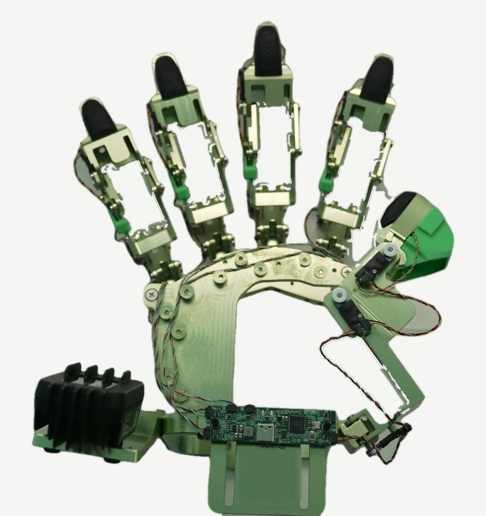
Example: right hand wired to the PCB

Right hand with the encoder wiring connected to the PCB
Wired to the PCB
Right hand with the encoder wiring routed through the palm
Routed through the palm

Which screws to use

Purpose / locationScrewNotes
DU-02-06 (fingertip)M1.6 x 3 mm countersunkApply red Loctite; secures DU-02-06 (step 9)
Standoff to top knuckle plateM3 x 12 mm countersunkApply blue Loctite; attaches the top knuckle plate to the standoffs (step 27)
Standoff to palm plate (bottom)M3 x 8 mm countersunkApply blue Loctite; secures the standoff to the palm plate (step 20)
Top knuckle plateM2 x 5 mm Phillips countersunkApply blue Loctite; locks the knuckle plates (step 26)
Attaching thumb to palmM2 x 6 mm socket headBase of the thumb mount
EncodersM1.2 x 6 mm flat headHolds the adapter head and encoder (#5, #8, #11, #14)
Palm mount (DU-01-02) to palm plateM2 x 6 mm hexFour screws (palm mount assembly, step 2)

Testing

Firmware installation and PCB flashing

Procedure for installing the firmware and flashing the palm PCB.

Coming soon The palm firmware (dexumi-hand-firmware) is not released yet. The steps below apply once it is.

StepPhaseActionTarget / command / pathExpected result
1Environment setupDownload and install editorVisual Studio Code (VS Code)VS Code installed and opens properly
2Workspace setupOpen the firmware workspace folderOpen folder: dexumi-hand-firmwareRepository tree visible in the Explorer sidebar
3ExtensionsInstall the required compiler and board extensionsC/C++ and Raspberry Pi Pico extensionsExtensions enabled in the VS Code extensions tab
4ConfigurationNavigate to the common header fileBoards -> dexumi_palm_common.hConfiguration file opens without error
5Terminal MenuOpen the run task menuClick "Terminal Menu" -> Run TaskTask picker opens in the command palette
6FlashingRun the compile and flash taskSelect: compile and flashBuild process runs in the terminal window
7Hardware connectAuthorize the device connectionClick "Allow" on the device promptPico PCB recognized by the system
8VerificationConfirm the firmware loaded and restartedMonitor the terminal output until progress reaches 100%"Device was rebooted to start application"

Hardware checks

Run these checks on every finished hand before use.

1

Check the build

All parts fit together and sit sturdy, with nothing loose.

2

Check the fit on the calibration tool

The hand fits the calibration tool exactly and the fingers do not bounce back up.

3

Connect the hand monitor

Plug the hand into a PC over USB and run the hand monitor tool: ./run.sh (Mac, Linux) or run.bat (Windows). It opens a live dashboard in your web browser.

Requirements

  • Python 3.6 or newer
  • A web browser
SystemOne-time setup
MacIf Python 3 is missing, run xcode-select --install. If run.sh will not start, run chmod +x run.sh.
LinuxRun sudo usermod -aG dialout $USER and log back in, or the serial port will not open.
WindowsNothing extra to install. The optional terminal view (--tui) needs pip install windows-curses.

Note You can unplug the USB or swap encoder cables while it runs.

4

Check the encoders

Every encoder reads, shows no drift while the hand is still, and its green light is on.