Load the filament
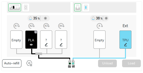
Load your Bambu H2D with PLA Basic and TPU 90A.
Click a part to jump to the steps that build it. Drag to rotate, scroll to zoom.
Part numbers, vendors and links are in the Bill of Materials.
Load your Bambu H2D with PLA Basic and TPU 90A.
Download UMI Open Source Printed Parts.3mf and the gripper STL files (ZIP). Unpack the STL files.
Open UMI Open Source Printed Parts.3mf in Bambu Studio.
To print the flexure grip and the gear mount as combined multi-part assemblies, select all of their .STL files (in the flexure grip and gear folders of the STL ZIP) and import them at the same time. Click Yes when asked to load the files as a single object with multiple parts.
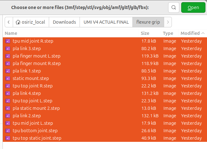
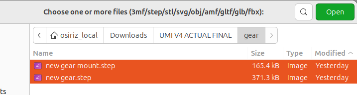
Note The gear and gear mount print together as one print-in-place part. Do not try to separate them.
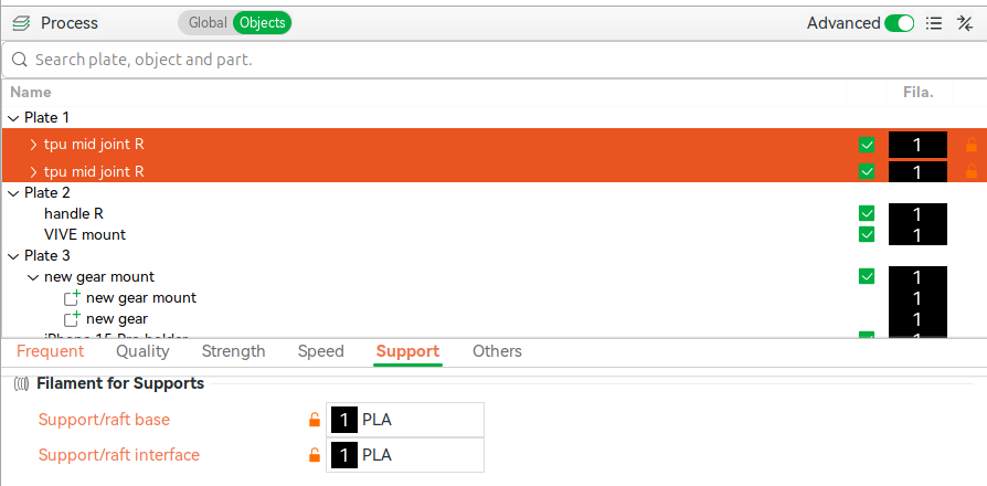
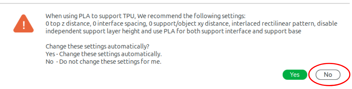
Download finger.3mf and open it in Bambu Studio.
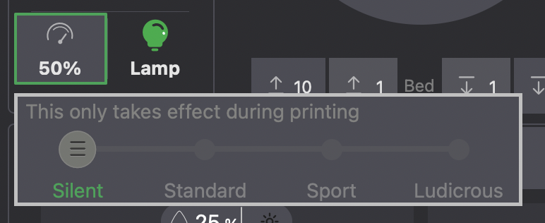
Print the remaining PLA parts in their current orientation, with default PLA supports.
Remove the supports from the finished parts.
See also the filament and print profile section of the Bill of Materials.
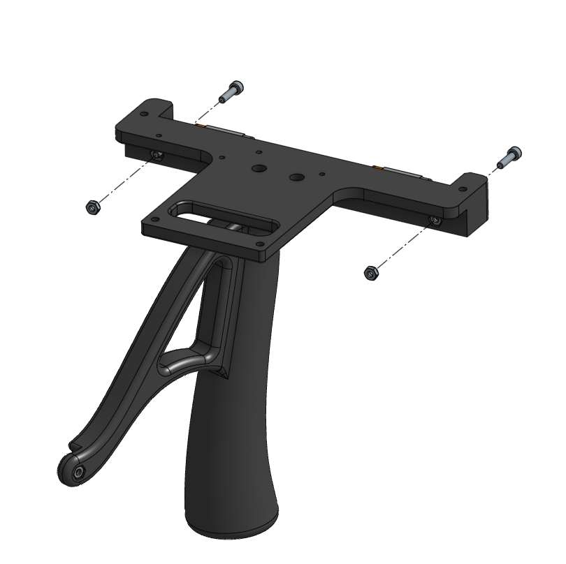
Fasten the MGN9 rail to the handle with two M3 x 12 mm hex socket cap screws and two M3 nuts.
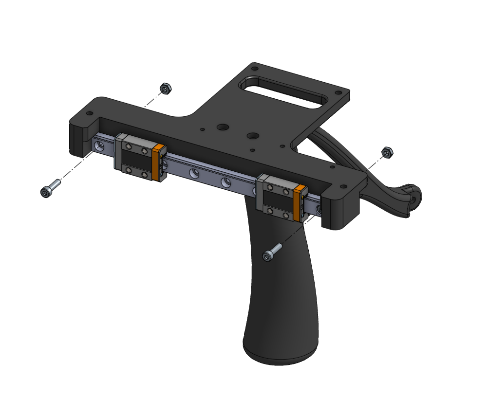
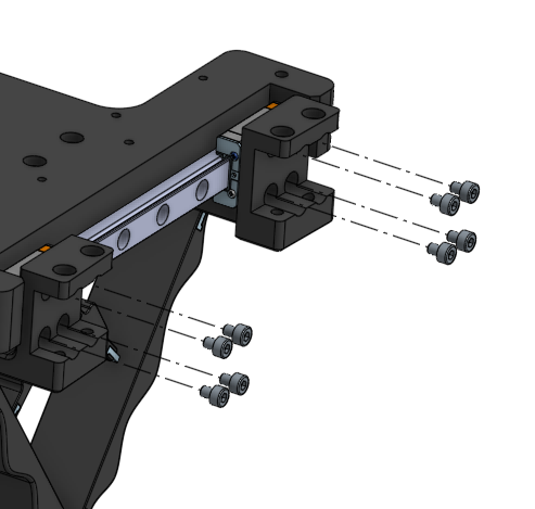
Fasten the finger mounts to the rail with eight M3 x 6 mm screws.
Fasten the flexure linkage to the center fastening holes with two M3 x 8 mm screws and two M3 nuts.
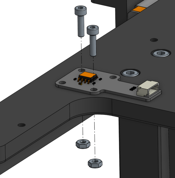
Fasten the rotary encoder board to the handle with two M2 x 8 mm screws and two M2 nuts.
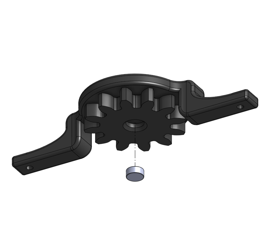
Super glue the magnet to the gear, then grease the gear and its mount for smooth rotation.
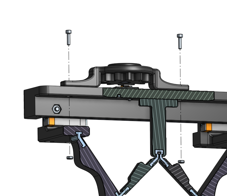
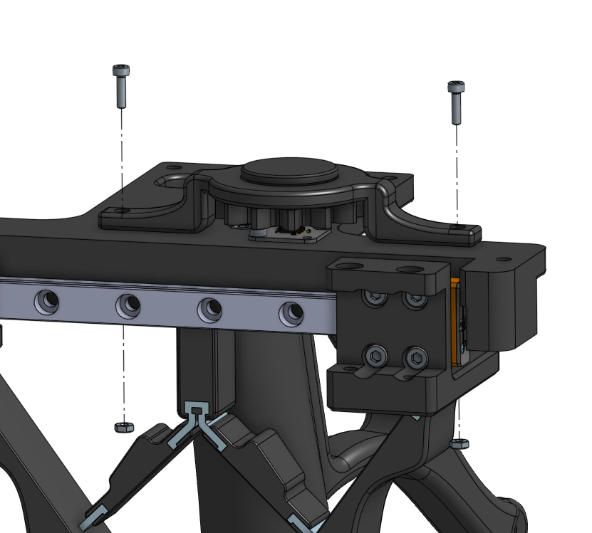
Fasten the gear to the handle with two M2 x 8 mm screws and two M2 nuts.
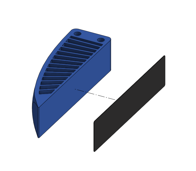
Cut the grip tape to shape with scissors and stick it on the fingers.
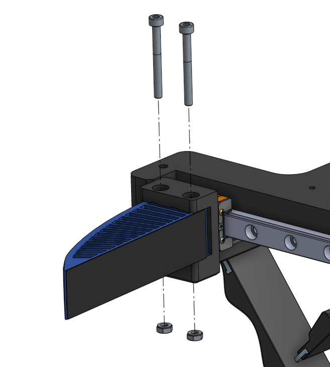
Fasten the left finger to the left finger mount with two M3 x 30 mm screws and two M3 nuts.
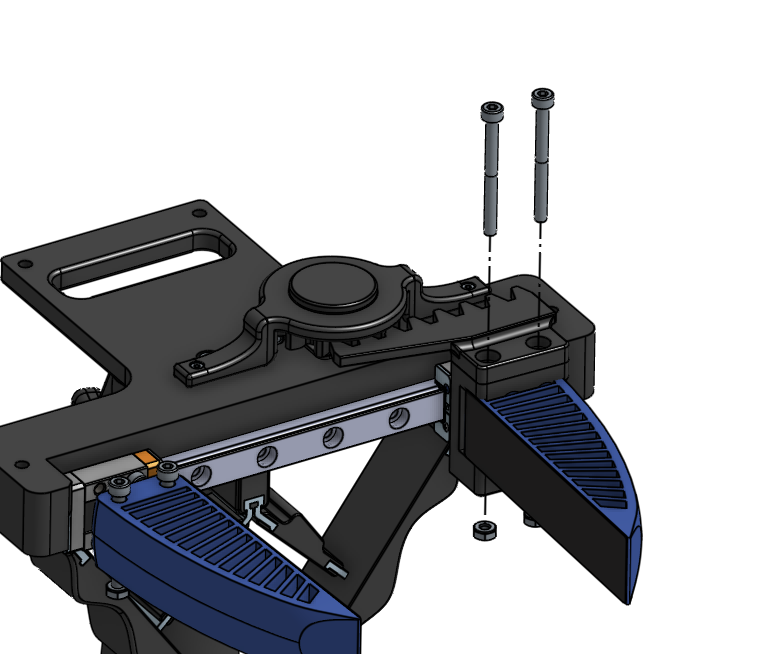
Fasten the right finger and the rack on top of the right finger mount with two M3 x 35 mm screws and two M3 nuts.
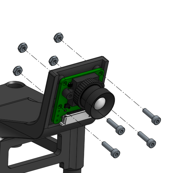
Fasten the top camera to the top camera mount with four M2 x 8 mm screws and four M2 nuts.
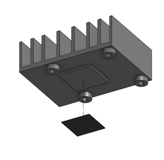
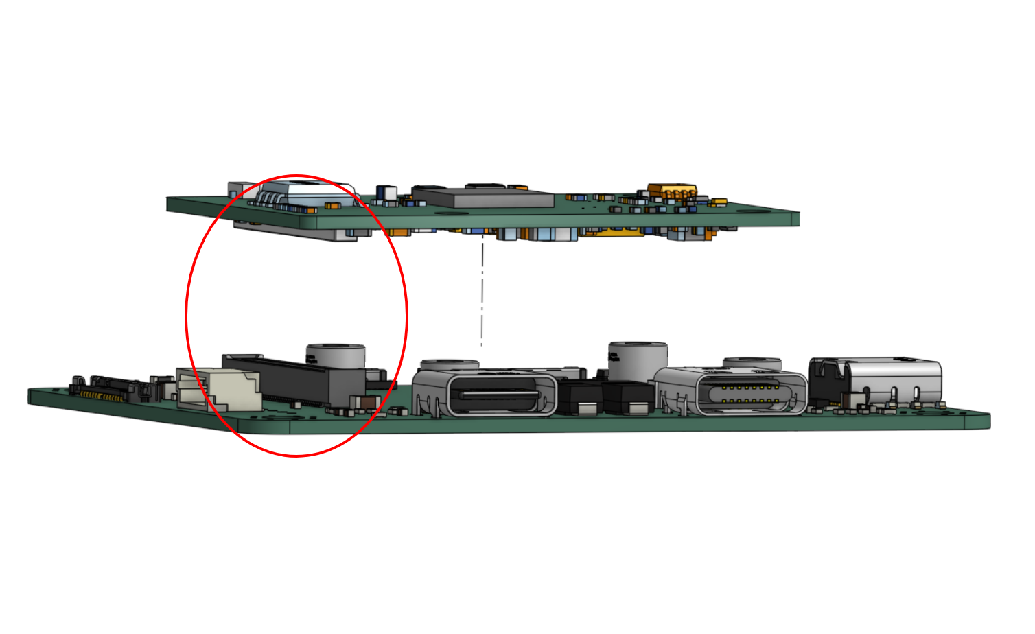
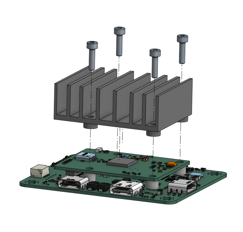
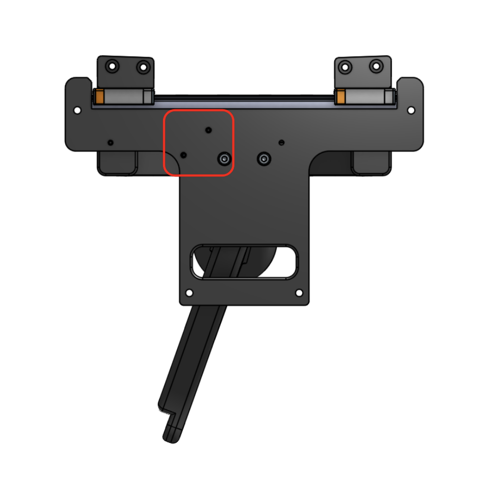
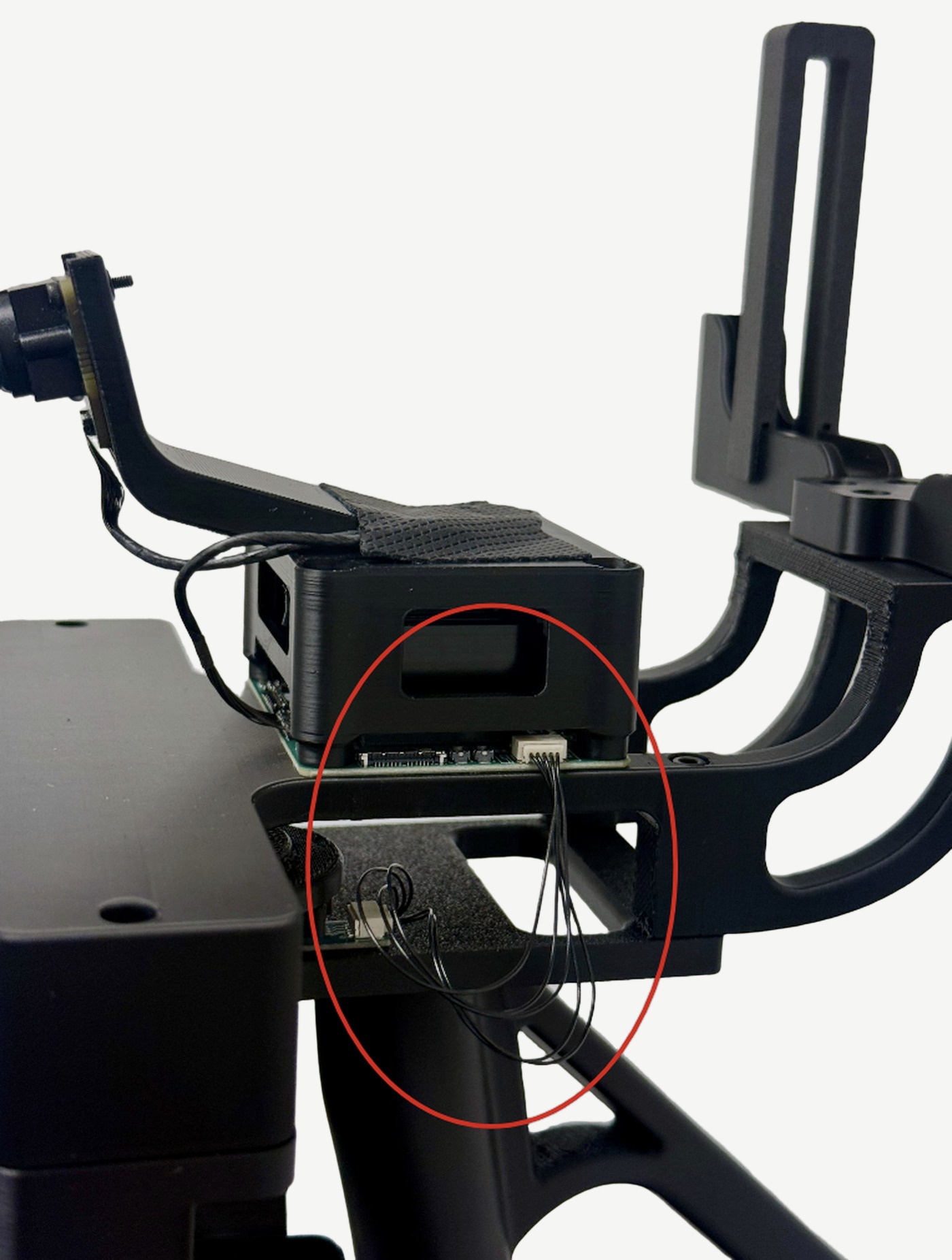
Plug the top camera cable into the main PCB board. The circled area in the photo shows the connection.
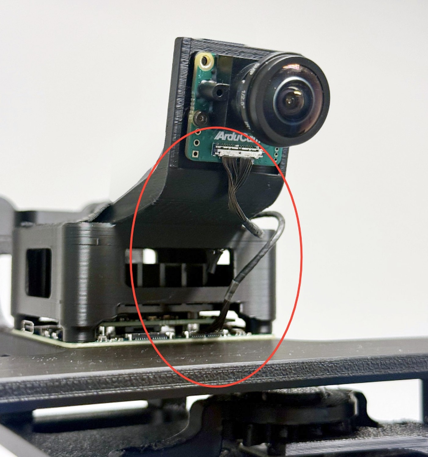
Fasten the top camera mount, with the PCB board, to the top cover with four M3 x 16 mm screws and four M3 nuts.
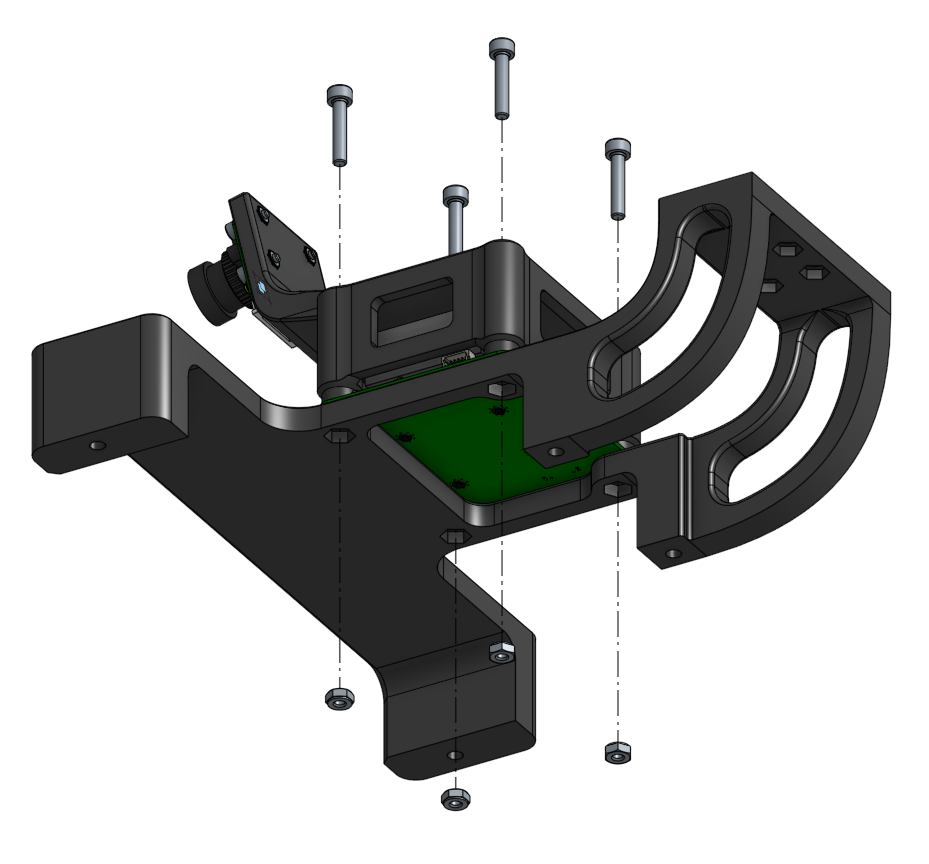
Fasten the wide camera to the trigger camera mount with three M2 x 6 mm hex socket screws and three M2 nuts.
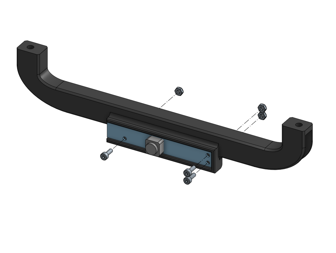
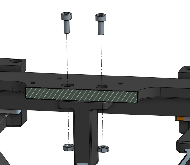
Fasten the top cover to the handle with two M3 x 30 mm hex socket cap screws and two M3 nuts.
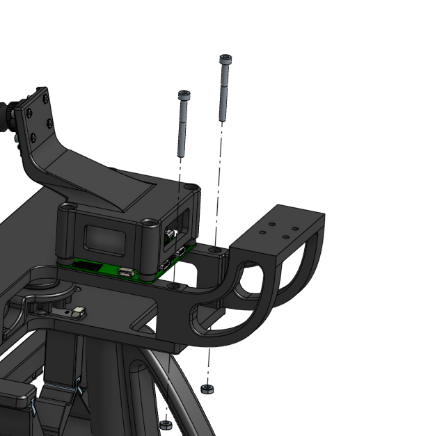
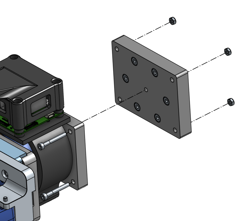
Fasten the top cover, the handle and the trigger camera mount together with two M3 x 35 mm screws and two M3 nuts, as shown.
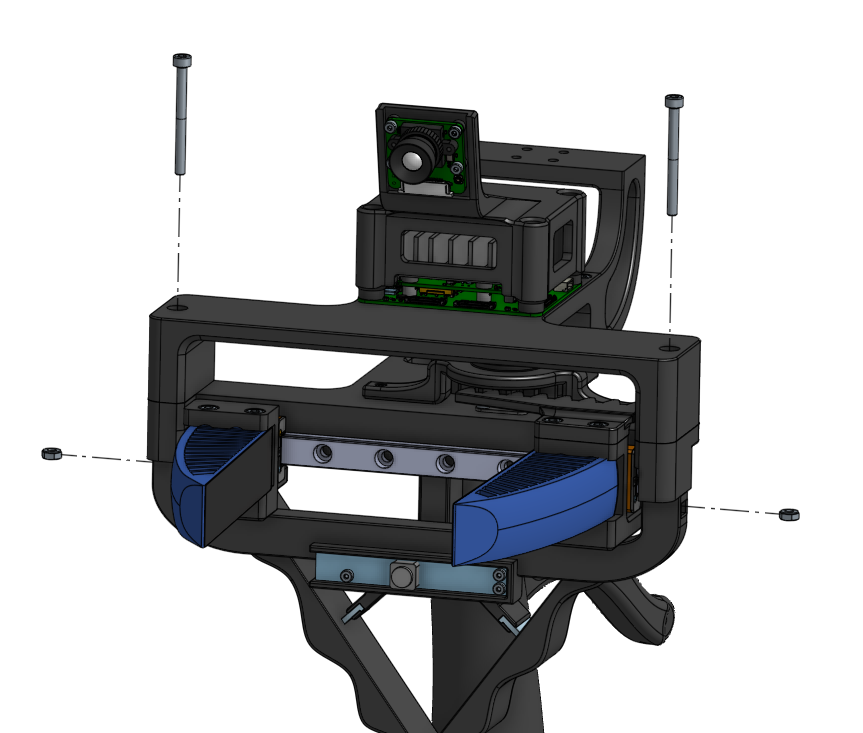
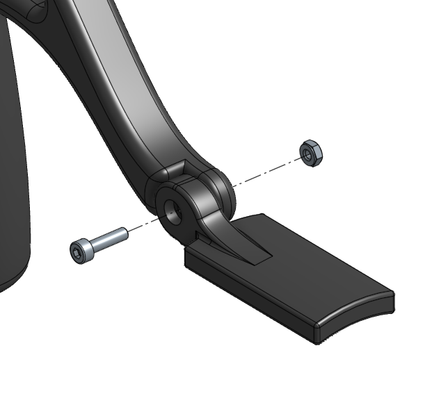
Fasten the handle link with one M3 x 12 mm screw and one M3 nut.
Fasten the iPhone mount on top of the top cover with four M3 x 12 mm screws and four M3 nuts, then attach the iPhone and the clip.
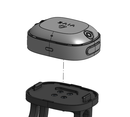
VIVE tracker: if you use the VIVE tracker mount instead, fasten it the same way, with four M3 x 12 mm screws and four M3 nuts.
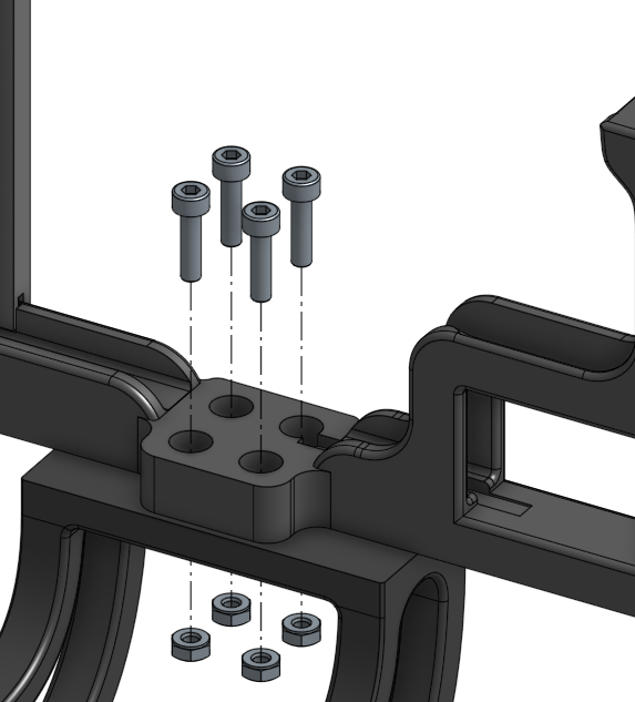
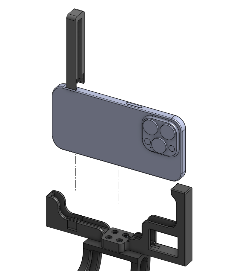
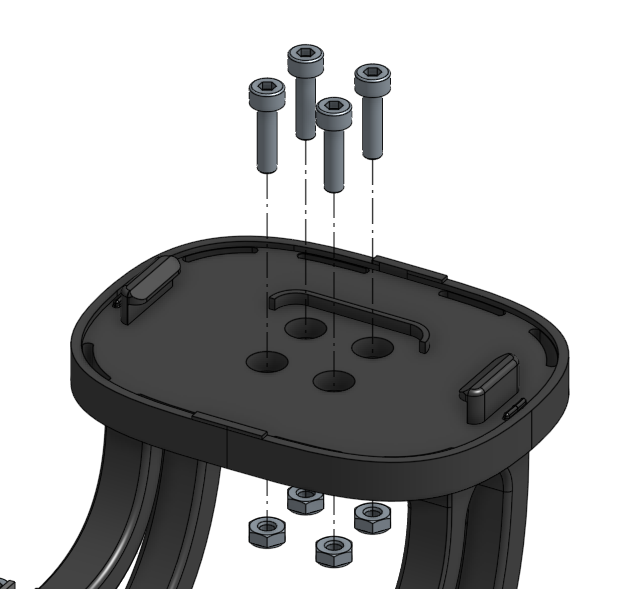
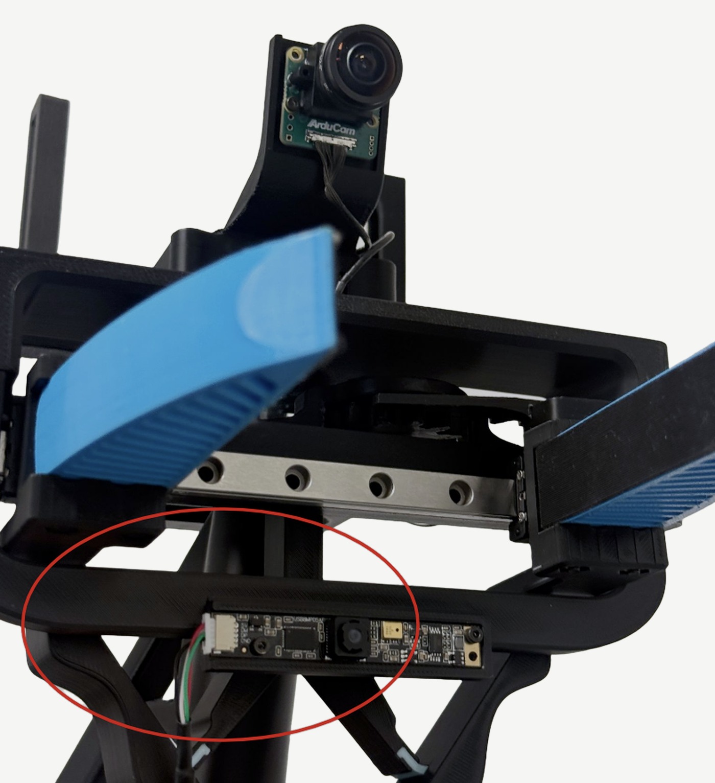
The circled areas in the photos show each connection, in the same order.
Put your thumb through the thumb loop of the wrist wrap strap, wrap the strap once around your wrist, then wrap it around the forearm mount.
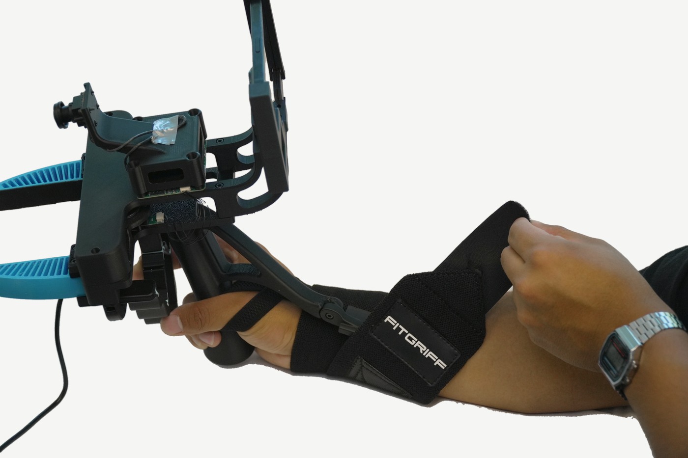
This builds the second gripper of the pair.
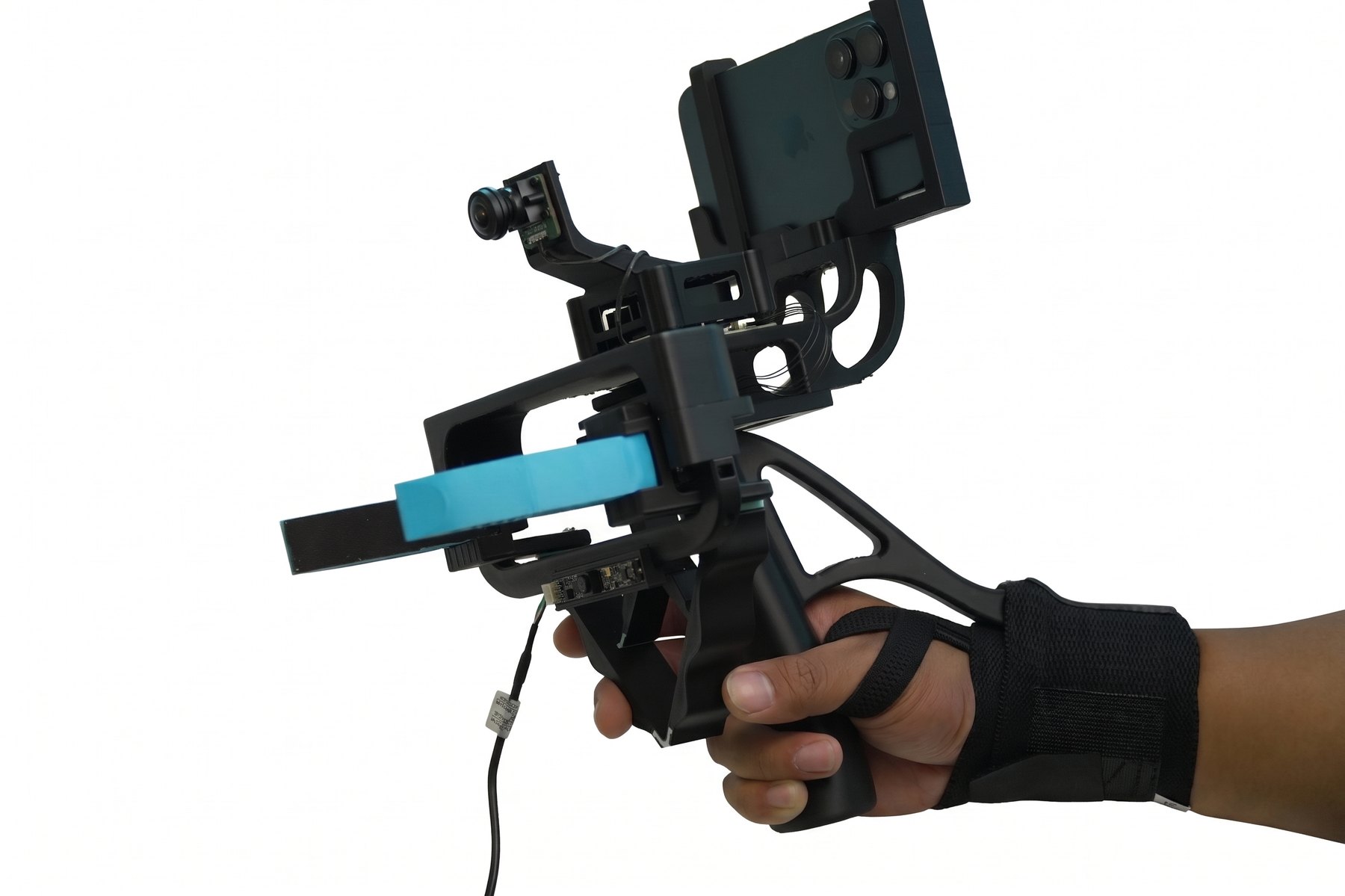
The RP2040 microcontroller on the UMI-OAK-CB1 main PCB runs the umi-encoder firmware, version 2.0.0 (electronics release Rev2617). It reads the TLE5012B rotary encoder 120 times a second and records the two on-board microphones, and sends both to the computer over USB. The encoder PCB has no microcontroller, so it needs no firmware of its own.
Note The release does not include a ready-to-flash firmware file. Build umi-encoder.uf2 from the source first, then flash it.
| File | Contents | Size |
|---|---|---|
| umi-encoder-v2.0.0-source.zip | Firmware v2.0.0: RP2040 sources and CMake build files | 68 KB |
| umi-oak-cb1-production.zip | UMI-OAK-CB1 main PCB: Gerbers, drill files, BOM and placement | 0.7 MB |
| tle5012b-encoder-production.zip | TLE5012B encoder PCB: Gerbers, drill files, BOM and placement | 30 KB |
| UMI-Gripper-Rev2617-offline.zip | Full release: KiCad projects for both boards, custom library and firmware | 7.7 MB |
| UMI-Gripper-Rev2617-README.md | Release notes: board architecture, USB interfaces, encoder data format | 5 KB |
The same files are in this repository, unzipped: the firmware in files/firmware/umi-encoder/ and the KiCad projects in files/electrical/kicad/. Keep the kicad/ folder structure as it is, so the boards find their custom library. Open them in KiCad 10 or newer.
arm-none-eabi)git clone -b 2.2.0 --recurse-submodules https://github.com/raspberrypi/pico-sdk.git ~/pico-sdkTip The Raspberry Pi Pico extension for VS Code installs the same SDK, toolchain and picotool versions for you, and the firmware’s build files pick them up automatically.
Unzip umi-encoder-v2.0.0-source.zip, then run these commands in the unzipped folder (the one that contains firmware/):
export PICO_SDK_PATH=~/pico-sdk
cmake -S firmware -B build -DCMAKE_BUILD_TYPE=Release
cmake --build build
The firmware file is build/umi-encoder.uf2. The encoder and the microphones are both on by default; the pin assignments are in firmware/board.h.
Connect the gripper to your computer with a cable in the main PCB's USB-C data port. The other USB-C port only supplies power, so the RP2040 can't be reached through it.
Use this when the gripper already runs UMI firmware. Install picotool 2.2.0 or newer, then run:
picotool load -f -x build/umi-encoder.uf2-f restarts the RP2040 into its USB bootloader (BOOTSEL mode) over the USB cable, and -x starts the new firmware when the copy is done. On Linux, run it with sudo if picotool can’t open the device.
Use this for a new board with no firmware yet, or if picotool can’t find the gripper.
RPI-RP2 appears. Copy build/umi-encoder.uf2 onto it.picotool info -fThe output should show the program name umi-encoder and version 2.0.0.
The gripper shows up on the computer as two serial ports and a microphone:
umi_protocol.h for the format.Check the sensor health in each frame before you trust its angle.
Click a part to jump to the steps that build it. Drag to rotate, scroll to zoom.
Part numbers, vendors and links are in the Bill of Materials. Print the fingers first, following print steps 6 and 7 in the Gripper tab.
Quantities are for one wrist. Build a second one for a pair.
Starting with the YAM gripper, unfasten the left and right finger tips.
Note Keep the dowel pins. You need them in step 2.
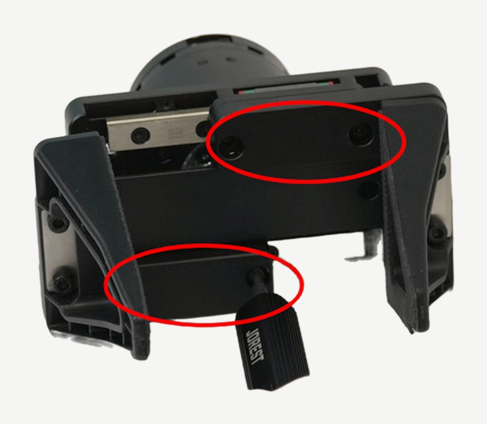
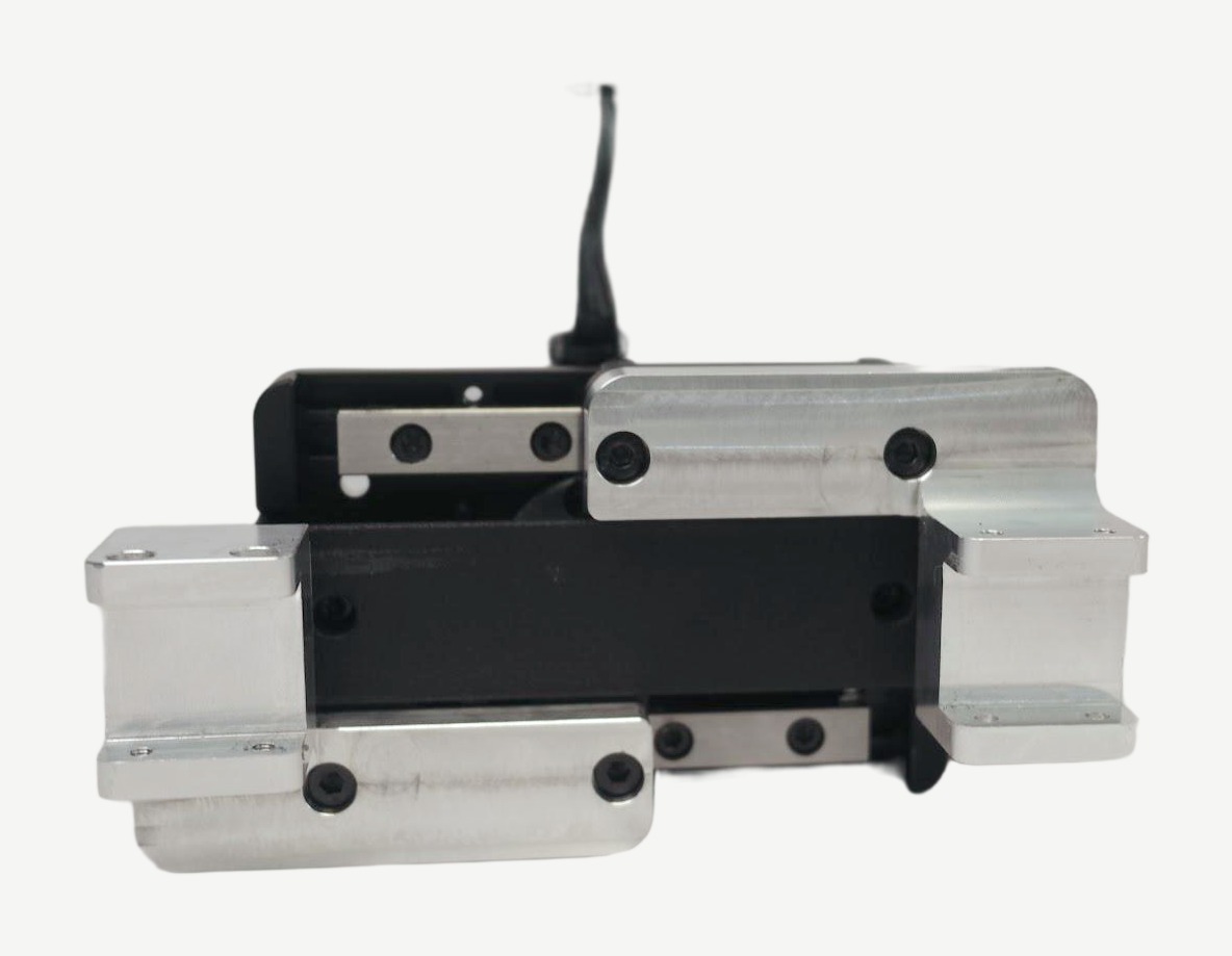
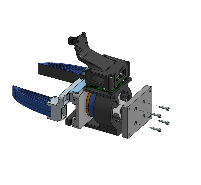
Fasten the finger mounts to the YAM linear gripper with four M4 x 15 mm hex socket cap screws, using the two dowel pins from step 1.
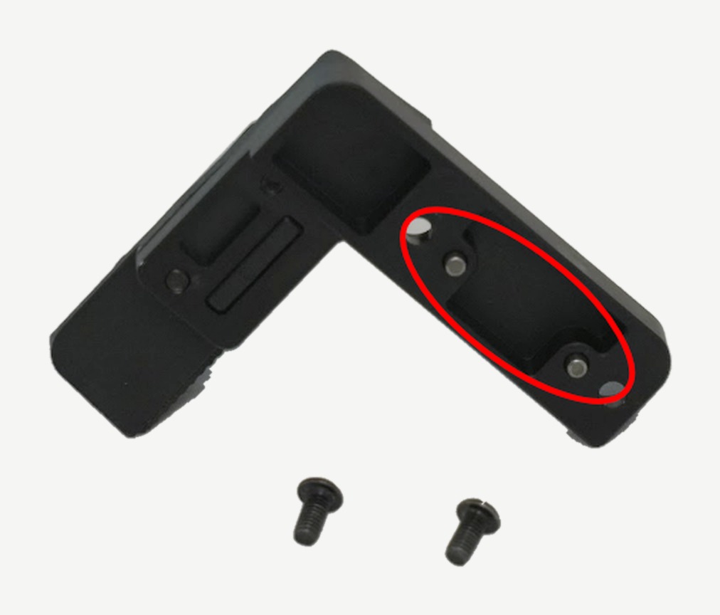
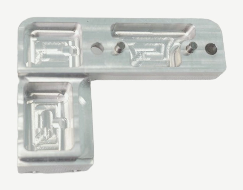
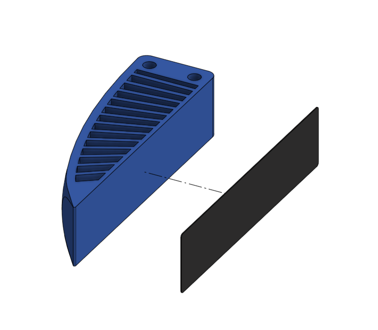
Cut the grip tape to fit with scissors and stick it on each finger as shown.
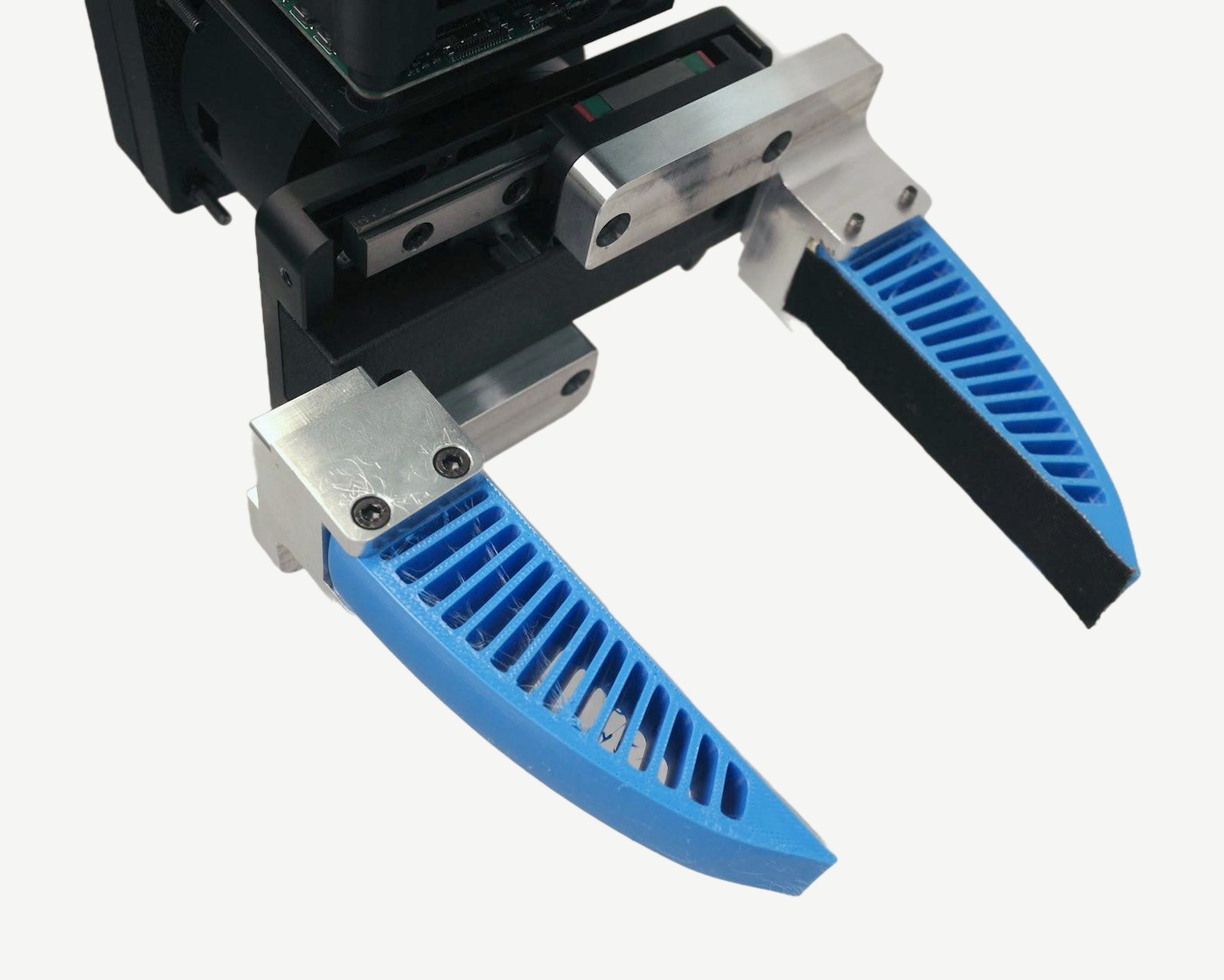
Slide each finger into its finger mount as shown, then fasten both with four M3 x 30 mm hex socket cap screws.
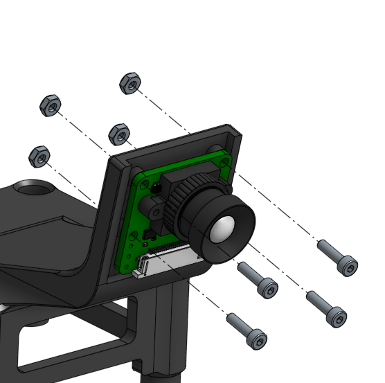
Fasten the top camera to the top camera mount with four M2 x 8 mm screws and four M2 nuts.
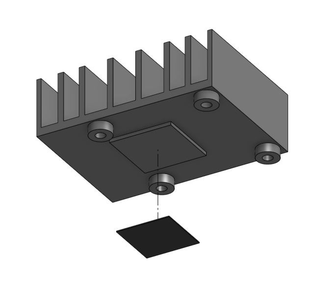
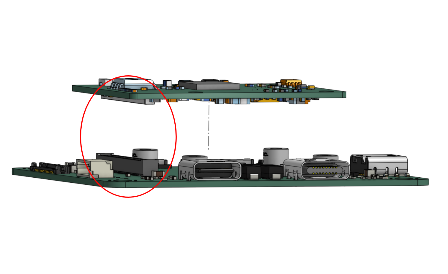
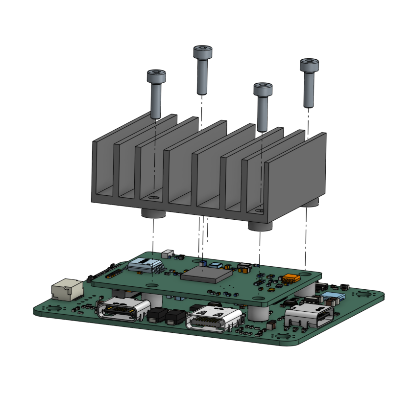
Fasten the top camera mount, with the PCB board, onto the wrist mount with four M3 x 18 mm hex socket cap screws and four M3 nuts.
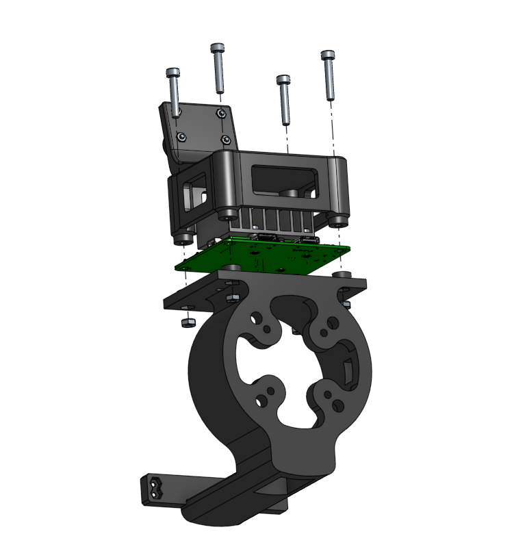
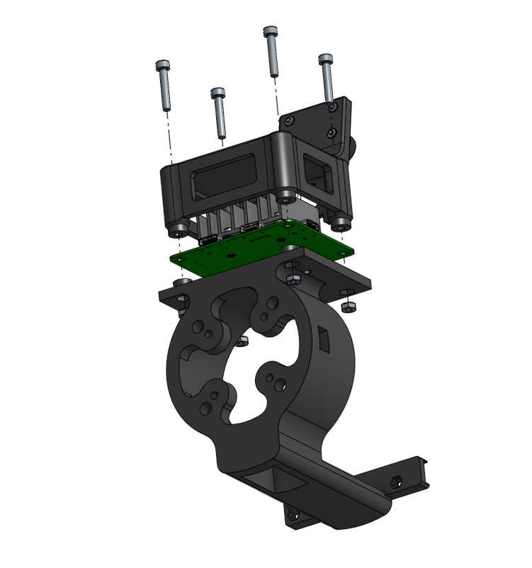
Fasten the trigger camera to the wrist mount with three M2 x 6 mm hex socket cap screws and three M2 nuts.
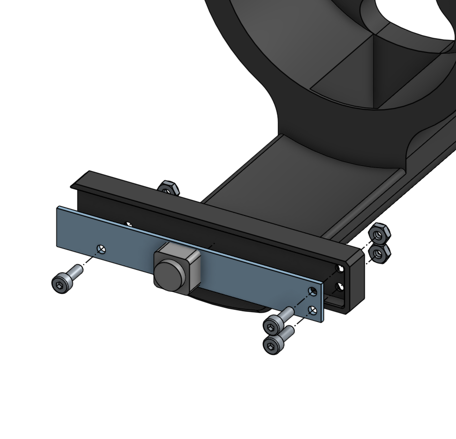
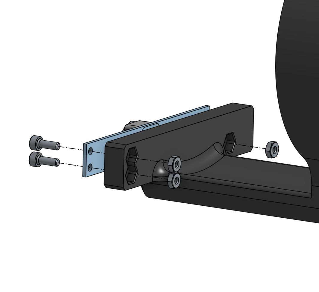
Fasten the wrist mount to the wrist with four M3 x 14 mm hex socket cap screws.
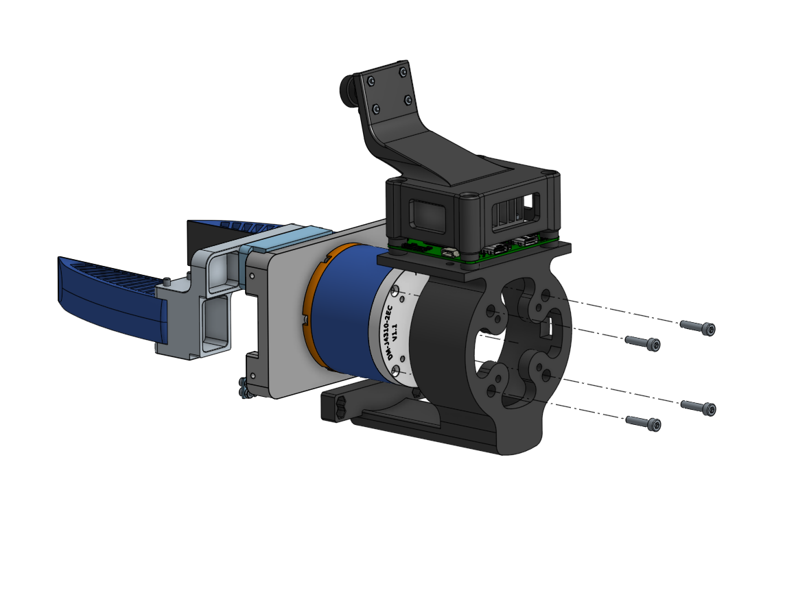
Fasten the wrist padding to the wrist mount with four M3 x 14 mm hex socket cap screws.
Fasten the Tianji mount to the robot arm with six M4 x 8 mm hex socket cap screws.
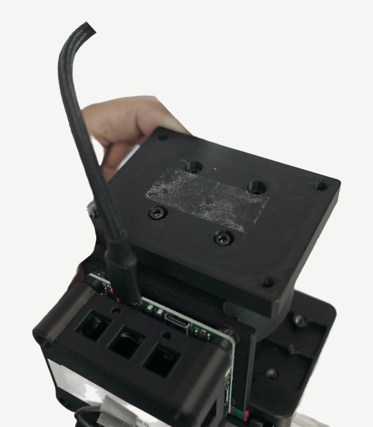
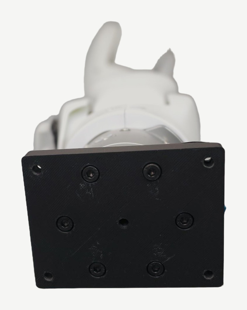
Fasten the whole wrist to the wrist padding with four M3 x 25 mm hex socket cap screws and four M3 nuts.