Mate the Yaw Actuator to the Base Bracket
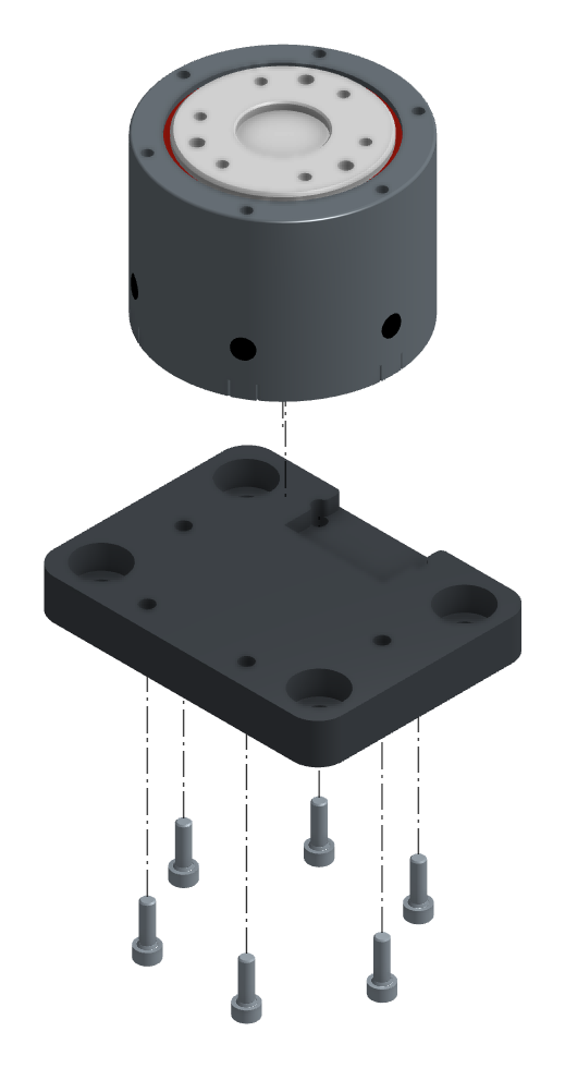
Fasten the Yaw Actuator (CAN ID 50) to the Base Bracket with six M2.5×8 screws from underneath.
Click a part to jump to the step that builds it. Drag to rotate, scroll to zoom.
Refer to the Bill of Materials section for 3D files and drawings to manufacture the necessary parts for this assembly.
Important step before you begin: Each actuator must be calibrated before the neck is assembled - follow the Motor Bring-Up section in the software guide.
Fasten the Yaw Actuator (CAN ID 50) to the Base Bracket with six M2.5×8 screws from underneath.
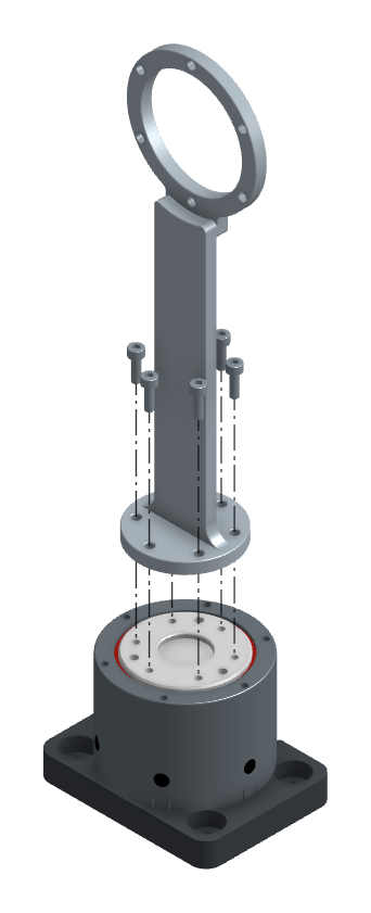
Fasten the Yaw Bracket to the top of the Yaw Actuator with six M2.5×8 screws.
Fasten the Roll Actuator (CAN ID 52) to the ring of the Yaw Bracket with six M2.5×8 screws.
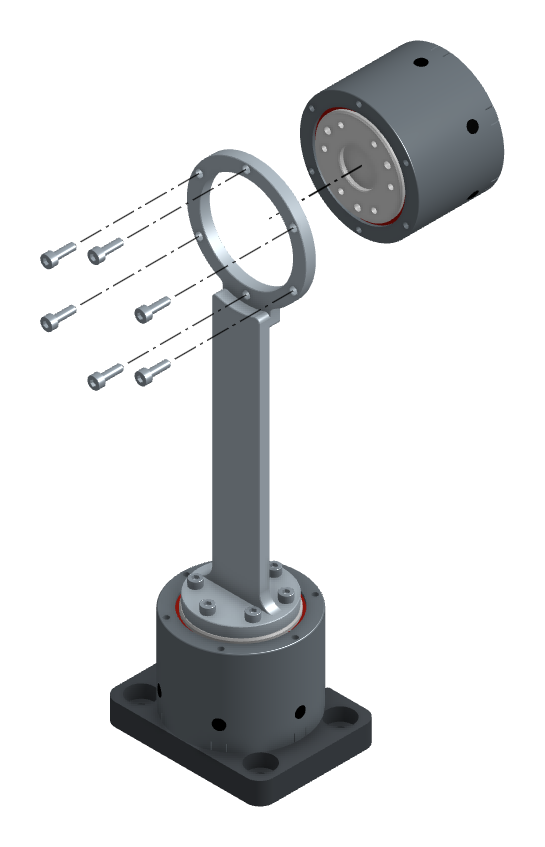
Fasten the Roll Bracket to the Roll Actuator with five M2.5×8 screws.
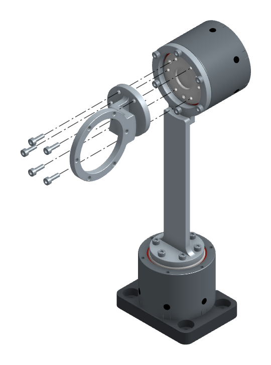
Fasten the Pitch Actuator (CAN ID 54) to the Roll Bracket with six M2.5×8 screws.
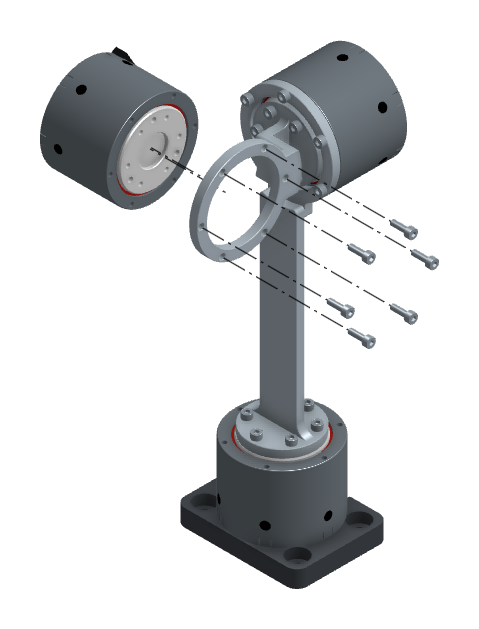
Fasten the Pitch Bracket to the Pitch Actuator with five M2.5×8 screws.
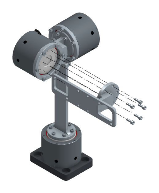
Fasten the two Cameras to the Pitch Bracket with four M2.5×6 screws, two per camera.
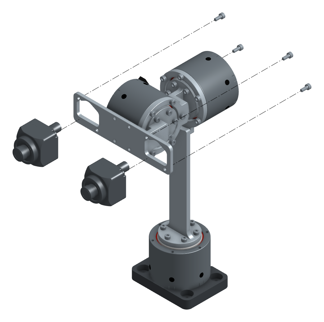
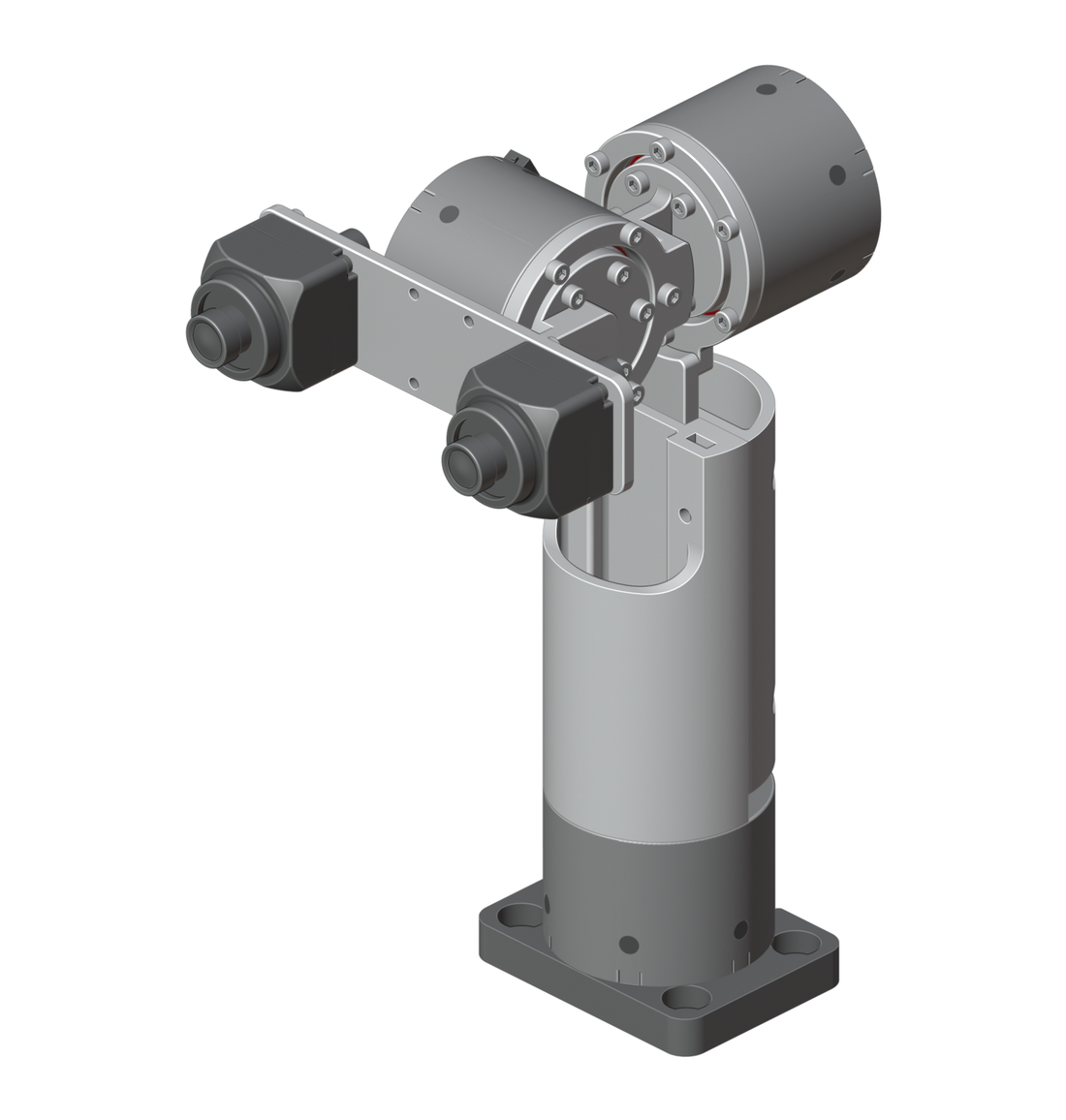
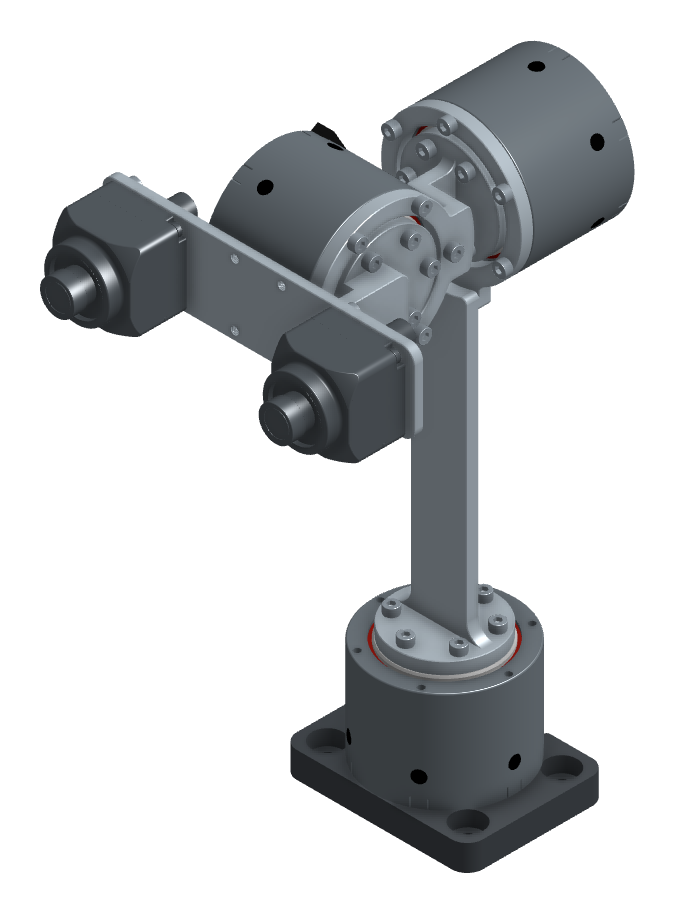
The neck is fully assembled: the base, the three actuators and their brackets, and both cameras.
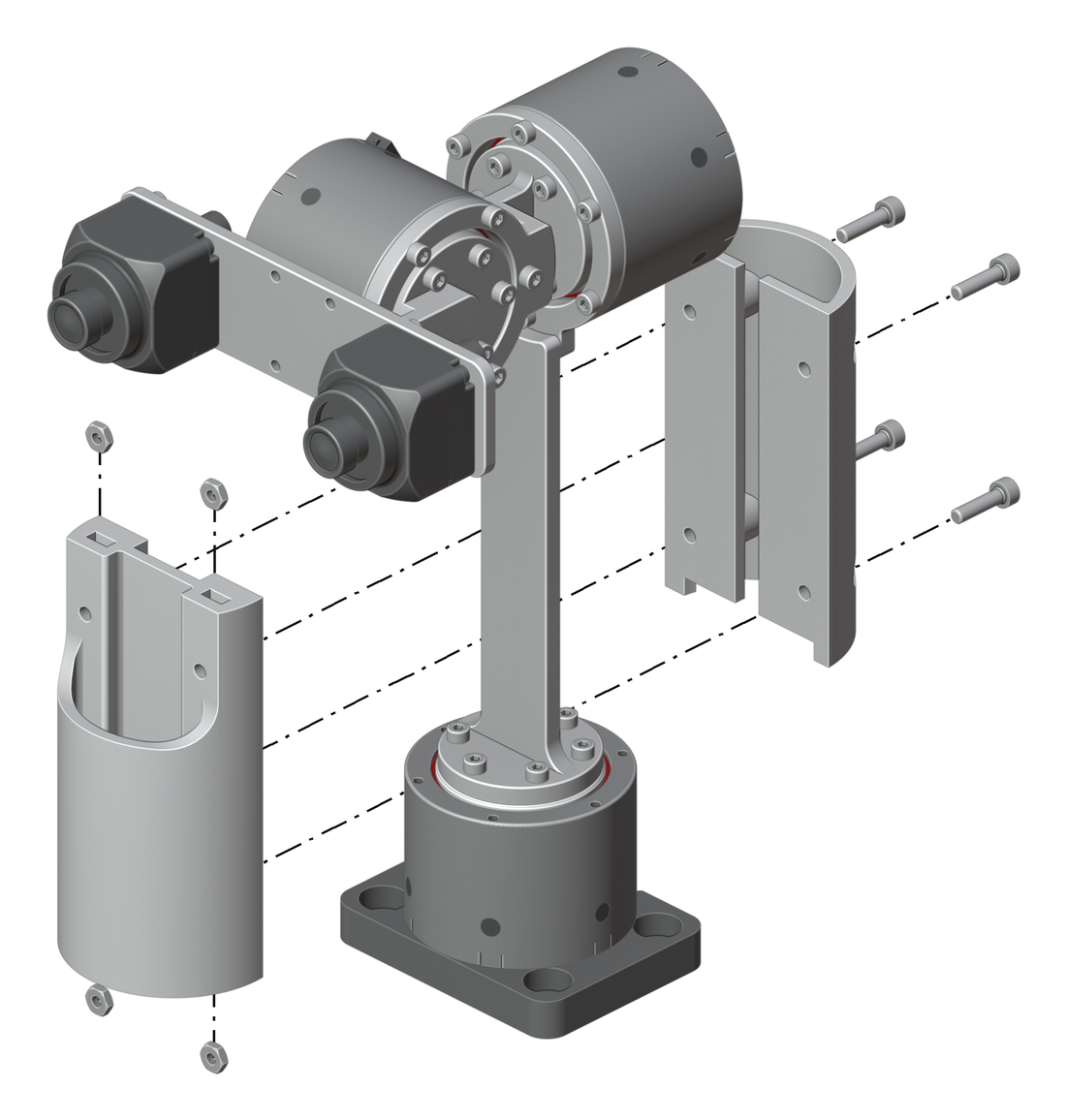
Next, build the wire harness, then home the neck with the Homing Fixture in the Software Guide. Install the Neck Cover last.
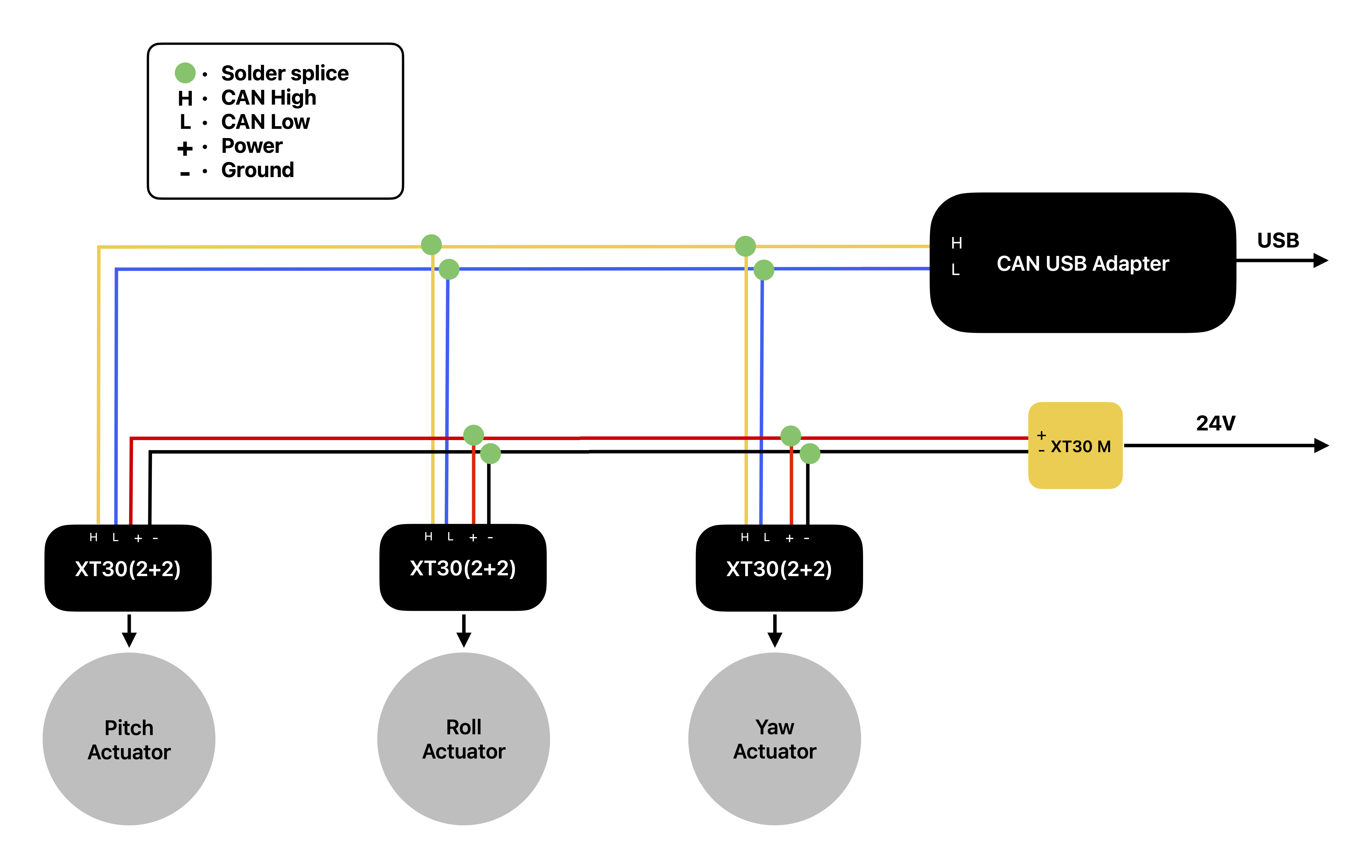
Construct the wire harness according to the interconnect diagram, leaving enough slack to allow ±90° of rotation on each actuator.
After homing The cover and the Homing Fixture take the same space around the Yaw Bracket, so home the neck first, take off the fixture and its two M2.5×6 screws, then fit the cover. Take the cover off again before homing the neck later.
Seat the four M3 thin nuts in the pockets of the Neck Cover Front. Close the front and the Neck Cover Back around the Yaw Bracket and clamp them together with four M3×12 screws from the back.